Introductory Circuit Analysis (13th Edition)
Introductory Circuit Analysis (13th Edition)
13th Edition
ISBN: 9780133923605
Author: Robert L. Boylestad
Publisher: PEARSON
expand_more
expand_more
format_list_bulleted
Bartleby Related Questions Icon
Related questions
Question
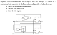
Transcribed Image Text:Sequential circuit shown below has two flip-flops A and B and one input x. It consists of a
combinatorial logic connected to the flip-flops, as shown in Figure below. Analyze the circuit:
a. Derive the next state and output equations.
b. The state table of the circuit.
c. Draw the state diagram.
A
A'
K
2to-1
, MUX Y
B
B'
CLK
lo
Expert Solution
Check MarkThis question has been solved!
Explore an expertly crafted, step-by-step solution for a thorough understanding of key concepts.
bartleby
This is a popular solution
bartleby
Trending nowThis is a popular solution!
bartleby
Step by stepSolved in 3 steps with 3 images
Knowledge Booster
Background pattern image
Learn more about
Need a deep-dive on the concept behind this application? Look no further. Learn more about this topic, electrical-engineering and related others by exploring similar questions and additional content below.Similar questions
- Table Q4(c) shows the parameters for three types of gates. Based on your decision on the speed- power product, which gate would you select for the best performance. Justify your answer. (c) Table Q4(c) tPLH tPHL PD Gate A 2 ns 2.4 ns 30 mW Gate B 10 ns S ns 16 mW Gate C 20 ns 20 ns 1 mWarrow_forwardDesign a combinational circuit using multiplexer for a car chime based on thefollowing system: A car chime or bell will sound if the output of the logic circuit(X) is set to a logic ‘1’. The chime is to be sounded for either of the followingconditions:• if the headlights are left on when the engine is turned off and• if the engine is off and the key is in the ignition when the door is opened.Use the following input names and nomenclature in the design process:• ‘E’ – Engine. ‘1’ if the engine is ON and ‘0’ if the engine is OFF• ‘L’ – Lights. ‘1’ if the lights are ON and ‘0’ if the lights are OFF• ‘K’ – Key. ‘1’ if the key is in the ignition and ‘0’ if the key is not in the ignition• ‘D’ – Door. ‘1’ the door is open and ‘0’ if the door is closed• ‘X’ – Output to Chime. ‘1’ is chime is ON and ‘0’ if chime is OFFarrow_forwardNeeds Complete solution with 100 % accuracy.arrow_forward
- Digital logic design Solve it with drawing and simulation lab I need them both to have the full solution. And thanks Design counter that counts from 00 to 59, using the IC 74LS90 ripple counter and use two 7 segment display to display the result count. You can also use 7447 binary to 7-segment Display Decoder.arrow_forward1. Design a combinational logic circuit with three inputs A, B and C and one output X. When only one input is 1, output is 1. When none of input is 1, output is also 1. Otherwise, output is 0.arrow_forwardplease explain part d and explain how it would look like on a breadboardarrow_forward
- 2. Explain which of the following instructions are invalid? State the invalidation reason and give the correct form for invalid instructions: a. MOV DL,AX b. MOV ES,CX c. MOV [BX],[2000] d. MOV BX,[AX] e. MOV CL,[BL+200] f. MOV 1234,DX g. MOV CH,[BX+SI+300] h. MOV DS,[SI+DI-5] i. MOV [4500],1234 j. MOV 200,[300]arrow_forwardcreate the schematic needed for part b and c pleasearrow_forwardA sequential logic circuit's outputs are dependent on both the inputs and the previous output. O a. Ob The only input is the clock signal. Previous experience with OC inputs. The sole data source is Od.arrow_forward
arrow_back_ios
arrow_forward_ios
Recommended textbooks for you
- Text book imageIntroductory Circuit Analysis (13th Edition)Electrical EngineeringISBN:9780133923605Author:Robert L. BoylestadPublisher:PEARSONText book imageDelmar's Standard Textbook Of ElectricityElectrical EngineeringISBN:9781337900348Author:Stephen L. HermanPublisher:Cengage LearningText book imageProgrammable Logic ControllersElectrical EngineeringISBN:9780073373843Author:Frank D. PetruzellaPublisher:McGraw-Hill Education
- Text book imageFundamentals of Electric CircuitsElectrical EngineeringISBN:9780078028229Author:Charles K Alexander, Matthew SadikuPublisher:McGraw-Hill EducationText book imageElectric Circuits. (11th Edition)Electrical EngineeringISBN:9780134746968Author:James W. Nilsson, Susan RiedelPublisher:PEARSONText book imageEngineering ElectromagneticsElectrical EngineeringISBN:9780078028151Author:Hayt, William H. (william Hart), Jr, BUCK, John A.Publisher:Mcgraw-hill Education,
Text book image
Introductory Circuit Analysis (13th Edition)
Electrical Engineering
ISBN:9780133923605
Author:Robert L. Boylestad
Publisher:PEARSON
Text book image
Delmar's Standard Textbook Of Electricity
Electrical Engineering
ISBN:9781337900348
Author:Stephen L. Herman
Publisher:Cengage Learning
Text book image
Programmable Logic Controllers
Electrical Engineering
ISBN:9780073373843
Author:Frank D. Petruzella
Publisher:McGraw-Hill Education
Text book image
Fundamentals of Electric Circuits
Electrical Engineering
ISBN:9780078028229
Author:Charles K Alexander, Matthew Sadiku
Publisher:McGraw-Hill Education
Text book image
Electric Circuits. (11th Edition)
Electrical Engineering
ISBN:9780134746968
Author:James W. Nilsson, Susan Riedel
Publisher:PEARSON
Text book image
Engineering Electromagnetics
Electrical Engineering
ISBN:9780078028151
Author:Hayt, William H. (william Hart), Jr, BUCK, John A.
Publisher:Mcgraw-hill Education,