Introductory Circuit Analysis (13th Edition)
Introductory Circuit Analysis (13th Edition)
13th Edition
ISBN: 9780133923605
Author: Robert L. Boylestad
Publisher: PEARSON
expand_more
expand_more
format_list_bulleted
Bartleby Related Questions Icon
Related questions
Question
expand button
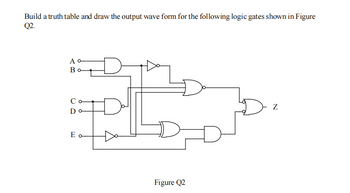
Transcribed Image Text:Build a truth table and draw the output wave form for the following logic gates shown in Figure
Q2.
A o
B
Co
Do
E o
D
D
Figure Q2
Z
Expert Solution
Check Markarrow_forward
Step 1
Electrical Engineering homework question answer, step 1, image 1
bartleby
Step by stepSolved in 3 steps with 3 images
Knowledge Booster
Background pattern image
Learn more about
Need a deep-dive on the concept behind this application? Look no further. Learn more about this topic, electrical-engineering and related others by exploring similar questions and additional content below.Similar questions
- Design a 2-bit multiplier with 2 2-bit inputs (X1X0 and Y1Y0) and gives out a 4-bit product (P3P2P1P0). Using ACT1 logic modules shown below only, no other gates are allowed. Intermediate logic module signals (F1, F2, and S) are not accessible to other logic modules.arrow_forwardDesign a 5 bits input logic circuit that can be output F to go active (High) under the following conditions: - All inputs are logic 1" - An odd number of inputs are logic 1" - Non of the inputs are logic 1"arrow_forward1. Consider the following two logic circuits. VDD A-6 B-d6 A-6 B-6 -6 -6 F VDD F t t A Circuit A Circuit B a. Do these two circuits implement the same logic function? If yes, what is that logic function? If no, give Boolean expressions for both circuits. b. Will these two circuits' output resistances always be equal to each other? c. Will these two circuits' rise and fall times always be equal to each other? Why or why not?arrow_forward
- Design the following combinational logic circuit with a four-bit input and a three-bit output. The input represents two unsigned 2-bit numbers: A1 A0 and B1 B0. The output C2 C1.C0 is the result of the integer binary division A1 A0/B1 B0 rounded down to three bits. The 3-bit output has a 2-bit unsigned whole part C2 C1 and a fraction part CO. The weight of the fraction bit CO is 21. Note the quotient should be rounded down, i.e. the division 01/11 should give the outputs 00.0 (1/3 rounded down to 0) not 00.1 (1/3 rounded up to 0.5). A result of infinity should be represented as 11.1. A minimal logic implementation is not required. (Hint: start by producing a truth table of your design).arrow_forwardNeeds Complete solution with 100 % accuracy.arrow_forward9 Part 1 of 2 Mc Graw Hill Required information Consider the logic gate circuit shown in the given figure. A (S1)-0- B (S2)-0 C (S3)-0- AB B BC B+C What is the Boolean equation for the given figure? ***************** The Boolean equation for the given figure is (Click to select) Note: This is a multi-part question. Once an answer is submitted, you will be unable to return to this part.arrow_forward
- 1. Design a combinational logic circuit with three inputs A, B and C and one output X. When only one input is 1, output is 1. When none of input is 1, output is also 1. Otherwise, output is 0.arrow_forward2. Explain which of the following instructions are invalid? State the invalidation reason and give the correct form for invalid instructions: a. MOV DL,AX b. MOV ES,CX c. MOV [BX],[2000] d. MOV BX,[AX] e. MOV CL,[BL+200] f. MOV 1234,DX g. MOV CH,[BX+SI+300] h. MOV DS,[SI+DI-5] i. MOV [4500],1234 j. MOV 200,[300]arrow_forwardWhat logic function is performed by this circuit? VDD a. O d. e. A b. None OC AB AB A+B A+B O f. B AB M1 M2 M3 M4 F M5arrow_forward
- Q1: Can you clearly show the answer to both parts of this questionarrow_forward#2arrow_forwardDesign a circuit that controls the passage of a signal "A" with the specifications: 1. Output X will equal A when control B and C are the same 2. X will remain HIGH when B and C are different. Hint: Set "A" input as a CLK pin.arrow_forward
arrow_back_ios
arrow_forward_ios
Recommended textbooks for you
- Text book imageIntroductory Circuit Analysis (13th Edition)Electrical EngineeringISBN:9780133923605Author:Robert L. BoylestadPublisher:PEARSONText book imageDelmar's Standard Textbook Of ElectricityElectrical EngineeringISBN:9781337900348Author:Stephen L. HermanPublisher:Cengage LearningText book imageProgrammable Logic ControllersElectrical EngineeringISBN:9780073373843Author:Frank D. PetruzellaPublisher:McGraw-Hill Education
- Text book imageFundamentals of Electric CircuitsElectrical EngineeringISBN:9780078028229Author:Charles K Alexander, Matthew SadikuPublisher:McGraw-Hill EducationText book imageElectric Circuits. (11th Edition)Electrical EngineeringISBN:9780134746968Author:James W. Nilsson, Susan RiedelPublisher:PEARSONText book imageEngineering ElectromagneticsElectrical EngineeringISBN:9780078028151Author:Hayt, William H. (william Hart), Jr, BUCK, John A.Publisher:Mcgraw-hill Education,
Text book image
Introductory Circuit Analysis (13th Edition)
Electrical Engineering
ISBN:9780133923605
Author:Robert L. Boylestad
Publisher:PEARSON
Text book image
Delmar's Standard Textbook Of Electricity
Electrical Engineering
ISBN:9781337900348
Author:Stephen L. Herman
Publisher:Cengage Learning
Text book image
Programmable Logic Controllers
Electrical Engineering
ISBN:9780073373843
Author:Frank D. Petruzella
Publisher:McGraw-Hill Education
Text book image
Fundamentals of Electric Circuits
Electrical Engineering
ISBN:9780078028229
Author:Charles K Alexander, Matthew Sadiku
Publisher:McGraw-Hill Education
Text book image
Electric Circuits. (11th Edition)
Electrical Engineering
ISBN:9780134746968
Author:James W. Nilsson, Susan Riedel
Publisher:PEARSON
Text book image
Engineering Electromagnetics
Electrical Engineering
ISBN:9780078028151
Author:Hayt, William H. (william Hart), Jr, BUCK, John A.
Publisher:Mcgraw-hill Education,