Electric Motor Control
Electric Motor Control
10th Edition
ISBN: 9781133702818
Author: Herman
Publisher: CENGAGE L
expand_more
expand_more
format_list_bulleted
Bartleby Related Questions Icon
Related questions
Question
create the schematic needed for part b and c please
Transcribed Image Text:OBJECTIVE:
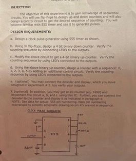
The objective of this experiment is to gain knowledge of sequential
circuits. You will use fip-flops to design up and down counters and will also
design a control crout to get the desired sequence of counting. You will
become familiar with 555 timer and use it to generate pulses
DESIGN REQUIREMENTS:
a. Design a clock pulse generator using 555 timer as shown.
b. Using JKp-flops, design a 4 bit binary down counter. Verify the
counting sequence by connecting LED's to the outputs.
c. Modify the above circult to get a 4-bit binary up-counter. Verify the
counting sequence by using LED's connected to the outputs
d. Using the above binary up counter, design a counter with a sequence: 0,
1, 2, 3, 4, 5 by adding an additional control circuit. Verity the counting
sequence by using LED'S connected to the outputs
e. (optional) You may connect the decoder and display, which you have
designed in experimenta 3. too verify your outputs
f. (optional) In addition, you may get an IC counter (eq 7490) and
Implement the circuit a, b, and cusing this IC. Further, you can connect the
decoder to the counter and display it as indicated in paragraph e
NOTE: See data for actual 555 pin numbering. Here in numbering
rearranged to simplify schematic drawing so pin a's are not in sequence.
CLOCK PIASE GENERASSA
everyt
Saur
445
COLA
Expert Solution
Check MarkThis question has been solved!
Explore an expertly crafted, step-by-step solution for a thorough understanding of key concepts.
bartleby
Step by stepSolved in 3 steps with 2 images
Knowledge Booster
Background pattern image
Learn more about
Need a deep-dive on the concept behind this application? Look no further. Learn more about this topic, electrical-engineering and related others by exploring similar questions and additional content below.Recommended textbooks for you
- Text book imageText book imageDelmar's Standard Textbook Of ElectricityElectrical EngineeringISBN:9781337900348Author:Stephen L. HermanPublisher:Cengage LearningText book imageElectricity for Refrigeration, Heating, and Air C...Mechanical EngineeringISBN:9781337399128Author:Russell E. SmithPublisher:Cengage Learning
- Text book imageEBK ELECTRICAL WIRING RESIDENTIALElectrical EngineeringISBN:9781337516549Author:SimmonsPublisher:CENGAGE LEARNING - CONSIGNMENTText book imagePower System Analysis and Design (MindTap Course ...Electrical EngineeringISBN:9781305632134Author:J. Duncan Glover, Thomas Overbye, Mulukutla S. SarmaPublisher:Cengage Learning
Text book image
Text book image
Delmar's Standard Textbook Of Electricity
Electrical Engineering
ISBN:9781337900348
Author:Stephen L. Herman
Publisher:Cengage Learning
Text book image
Electricity for Refrigeration, Heating, and Air C...
Mechanical Engineering
ISBN:9781337399128
Author:Russell E. Smith
Publisher:Cengage Learning
Text book image
EBK ELECTRICAL WIRING RESIDENTIAL
Electrical Engineering
ISBN:9781337516549
Author:Simmons
Publisher:CENGAGE LEARNING - CONSIGNMENT
Text book image
Power System Analysis and Design (MindTap Course ...
Electrical Engineering
ISBN:9781305632134
Author:J. Duncan Glover, Thomas Overbye, Mulukutla S. Sarma
Publisher:Cengage Learning