Showing posts with label Serial. Show all posts
Showing posts with label Serial. Show all posts
Monday, May 9, 2016
Android-Arduino Communication via USB OTG
USB On-the-go capability in Android devices has now become more available in the market. And why wouldn’t it be? This feature, nicknamed OTG, enables you to use your flash drives, keyboards, mice and even printers with just your phone! What’s more interesting is it can also enable you to communicate and control your microprocessors using your Android device without the need for additional modules – just a cable. In this article, we will see how this communication can become possible. To demonstrate, we will control the behavior of an LED and send messages to another very popular item in the electronics world – the Arduino.
The shorter end of the stick is Arduino’s side. In your Arduino, simply upload this code:
int ledPin = 13;
void setup(){
 Serial.begin(9600);
 Serial.setTimeout(200);
 pinMode(ledPin, OUTPUT);
}
void loop(){
 if (Serial.available()){
 String c = Serial.readString();
 if (c.equals("TONLED")) digitalWrite(ledPin, HIGH);
 else if (c.equals("TOFFLED")) digitalWrite(ledPin, LOW);
 else Serial.print(c);
 }
}
In the above sketch, we are simply waiting for the data arriving at our serial line and performing actions based on the data received. For instance, turning on the LED ledPin requires a TONLED message from our Android device. You’ve probably noticed that there are no special libraries or methods in our Arduino sketch. That’s a great thing because it tells us that the system is not exclusive to Arduino and will work with any microcontroller that supports serial communication.
Let’s now move on to Android’s side. The first step is to create an Android project and add the necessary components. In the project we created, we added extra components for user convenience. For learning and testing purposes, only the following are necessary:
- Text Field – used to get input data by the user, which will be sent to and echoed by the Arduino
- Toggle Button – used to control the behavior of the LED
- Start Button – used to open the serial port
- Send Button – used to send messages to Arduino
- Text View – used to display logs
To simplify the setup and processes, we will use the UsbSerial library by felHR85. There are a lot of libraries you can choose from. In case you have other preferences, feel free to modify and adapt to your preferred library.
In the build.gradle of your project, add jitpack. Jitpack is a very awesome tool that enables us to get a Git project into our build.
allprojects {
 repositories {
 jcenter()
 maven { url "https://jitpack.io" }
 }
}
Now, add the dependency to your module’s build.gradle.
compile 'com.github.felHR85:UsbSerial:4.3'
Moving on to our main activity, there are some variables that we wish to declare globally for convenience.
private static final String ACTION_USB_PERMISSION = "com.android.example.USB_PERMISSION";
UsbDevice device;
UsbDeviceConnection connection;
UsbManager usbManager;
UsbSerialDevice serialPort;
PendingIntent pendingIntent;
The next items that we will present here will not be discussed thoroughly, but you can refer to Android's official documentation for details.
Before trying to start the communication, you must seek permission from the user. To do this, create a broadcast receiver. This receiver listens for the intent that gets broadcasted when you call requestPermission(). Only when granted can we proceed to opening the connection and setting parameters for the Serial communication.
private final BroadcastReceiver broadcastReceiver = new BroadcastReceiver() {
 @Override
 public void onReceive(Context context, Intent intent) {
 if (intent.getAction().equals(ACTION_USB_PERMISSION)) {
 boolean granted = intent.getExtras().getBoolean(UsbManager.EXTRA_PERMISSION_GRANTED);
 if (granted) {
 connection = usbManager.openDevice(device);
 serialPort = UsbSerialDevice.createUsbSerialDevice(device, connection);
 if (serialPort != null) {
 if (serialPort.open()) {
 serialPort.setBaudRate(9600);
 serialPort.setDataBits(UsbSerialInterface.DATA_BITS_8);
 serialPort.setStopBits(UsbSerialInterface.STOP_BITS_1);
 serialPort.setParity(UsbSerialInterface.PARITY_NONE);
 serialPort.setFlowControl(UsbSerialInterface.FLOW_CONTROL_OFF);
 serialPort.read(mCallback);
 } else {
 Log.d("SERIAL", "PORT NOT OPEN");
 }
 } else {
 Log.d("SERIAL", "PORT IS NULL");
 }
 } else {
 Log.d("SERIAL", "PERMISSION NOT GRANTED");
 }
 } else if (intent.getAction().equals(UsbManager.ACTION_USB_DEVICE_ATTACHED)) {
 onClickStart(startButton);
 } else if (intent.getAction().equals(UsbManager.ACTION_USB_DEVICE_DETACHED)) {
 //can add something to close the connection
 }
 };
};
On your onCreate method, declare the intent and register your broadcast receiver to start and stop the serial connection.
pendingIntent = PendingIntent.getBroadcast(this, 0, new Intent(ACTION_USB_PERMISSION), 0);
IntentFilter filter = new IntentFilter(ACTION_USB_PERMISSION);
registerReceiver(broadcastReceiver, filter);
In our application, we created a start button to start the connection when pressed. In the method that corresponds to the onClick action of our button, we add the following:
public void onClickStart(View view) {
 if (!isSerialStarted) {
 usbManager = (UsbManager) getSystemService(Context.USB_SERVICE);
 HashMap<String, UsbDevice> usbDevices = usbManager.getDeviceList();
 if (!usbDevices.isEmpty()) {
 boolean keep = true;
 for (Map.Entry<String, UsbDevice> entry : usbDevices.entrySet()) {
 device = entry.getValue();
 int deviceVID = device.getVendorId();
 if (deviceVID == 1027 || deviceVID == 9025) { //Arduino Vendor ID
 usbManager.requestPermission(device, pendingIntent);
 keep = false;
 } else {
 connection = null;
 device = null;
 }
 if (!keep)
 break;
 }
 }
 }
}
The code above searches for vendor IDs 1027 or 9025 – the vendor ID’s associated to FTDI or Arduino. The vendor ID equal to 9025 is the more popular and more common value based on other articles in the internet, but mine has an ID of 1027. The easiest way to know is to just print the vendor IDs detected by the Android device. If the vendor ID matches the expected ID for our device, we will call the requestPermission() method. With this, the intent will be broadcasted and picked up by our receiver, starting and opening the connection.
Once communication is opened, we can start sending and receiving data. To receive from Arduino, simply add the codes below. Note that we are appending the data received to the text view.
private UsbSerialInterface.UsbReadCallback mCallback = new UsbSerialInterface.UsbReadCallback() {
 //Defining a Callback which triggers whenever data is read.
 @Override
 public void onReceivedData(byte[] arg0) {
 String data = null;
 try {
 data = new String(arg0, "UTF-8");
 data.concat("/n");
 tvAppend(displayView, data);
 } catch (UnsupportedEncodingException e) {
 e.printStackTrace();
 }
 }
};
private void tvAppend(final TextView tv, final CharSequence text) {
 runOnUiThread(new Runnable() {
 @Override public void run() {
 if (text != null) {
 tv.append(text);
 }
 }
 });
}
Sending data is easier. We only need to get user input from the text field, and send it to the connected device.
public void onClickSend(View view) {
 String textInput = inputView.getText().toString();
 serialPort.write(textInput.getBytes());
}
To control the LED in Arduino, simply add the code below. You are free to change TONLED and TOFFLED to whatever names you want. Just don’t forget to adjust the Arduino code as well.
public void onClickToggle(View view) {
 if (isLedON == false) {
 isLedON = true;
 tvAppend(displayView, "\nLED TURNED ON\n");
 serialPort.write("TONLED".getBytes());
 } else {
 isLedON = false;
 serialPort.write("TOFFLED".getBytes());
 tvAppend(displayView, "\nLED TURNED OFF\n");
 }
}
You can close the connection using:
serialPort.close();
We are almost done. In your manifest file, add the following so that your application will be notified of an attached USB device.
<?xml version="1.0" encoding="utf-8"?>
<manifest xmlns:android="http://schemas.android.com/apk/res/android"
 package="yourpackage.com.name">
 <uses-feature android:name="android.hardware.usb.host" />
 <application
 android:allowBackup="true"
 android:icon="@mipmap/ic_launcher"
 android:label="@string/app_name"
 android:supportsRtl="true"
 android:theme="@style/AppTheme">
 <activity
 android:name=".MainActivity"
 android:label="@string/app_name"
 android:theme="@style/AppTheme.NoActionBar">
 <intent-filter>
 <action android:name="android.intent.action.MAIN" />
 <category android:name="android.intent.category.LAUNCHER" />
 </intent-filter>
 <intent-filter>
 <action android:name="android.hardware.usb.action.USB_DEVICE_ATTACHED" />
 </intent-filter>
 <meta-data
 android:name="android.hardware.usb.action.USB_DEVICE_ATTACHED"
 android:resource="@xml/device_filter" />
 <intent-filter>
 <action android:name="android.hardware.usb.action.USB_DEVICE_DETACHED" />
 </intent-filter>
 </activity>
 </application>
</manifest>
Create an xml folder inside the res folder and add device_filter.xml
<?xml version="1.0" encoding="utf-8"?>
<resources>
 <usb-device
 vendor-id="9025"/>
</resources>
And… were done! Additional tips, we can add a checker to confirm that the serial connection is already open. This saves us from crashes due to attempts to send serial data while the connection is still closed. We can also add clear buttons, or place the text view inside a scroll view then automatically scroll to end of page using:
mScrollView.smoothScrollTo(0, displayView.getBottom());
That’s it. If you want to extend your phone’s sensors, or if you want to add storage, wireless and messaging capability, camera and orientation sensors in your microprocessor project with just one device, USB On-the-Go, may be your way to go.
A demo application, SimpleArDroid by YMSoftLabs can be downloaded from Google Play. Here's a video of how the system works.
[フレーム]
References:
UsbSerial: A serial port driver library for Android v3.0
USBSerial
Communicate with Your Arduino Through Android
Tuesday, March 29, 2011
Hello World, WM8505!
My first step in learning the ARM9 platform.
VIA / WonderMedia's WM8505 (ARM926EJ-S):
UART0 Connection:
Serial console connection details: Project Gus
Required Tools: all are free =)
The goal is to run this simple code: (main.c)
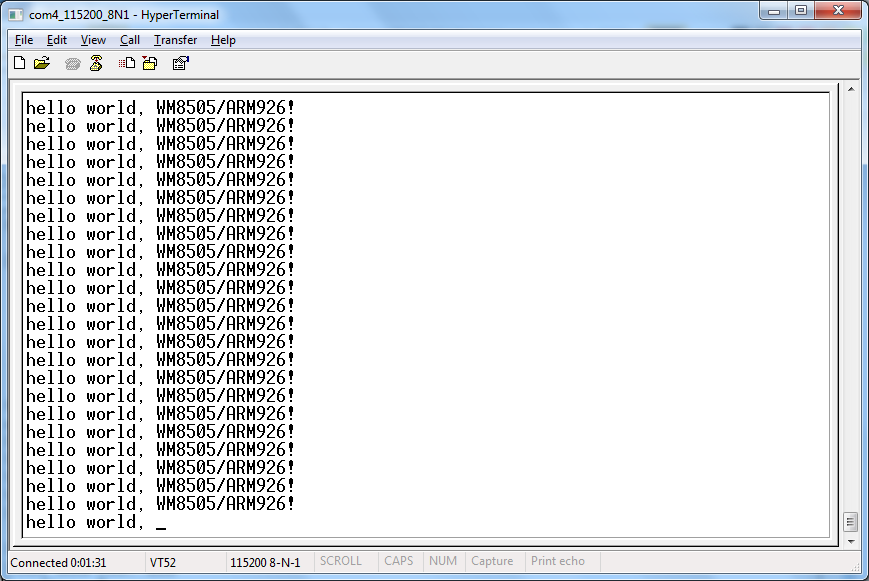
It should output these strings on UART_0 port, just like this:
After setting up the tools, here are the next steps:
-Create new project on Eclipse
-Select target processor (WM8505 is a ARM926EJ-S processor)
-Select binary format for the flash image:
-linker setting:
- after building the project, open the generated *.map file to verify the linker output
- Complete Eclipse project files:
download here: ARM9_WM8505_UART0.zip
* most of the hardware initializations (e.g. clock settings) are already done by the bootloader,
so we don't have to worry about them for now.
Next question is, "how to load and run the code?
I've tested two ways of how to transfer the generated image to the RAM:
First is through tftp transfer, second is SD card load during boot-up.
Both method uses the bootloader, which is already present in the board (in the SPI flash).
My board got v1.1.4 of U-BOOT.
1. TFTP transfer to RAM.
- get a copy of this freeTFTPD32 server application.
- using the LAN adapter, connect board to host PC Ethernet
enter u-boot console, and type these commands:
* RAM load address can use other than 0x0
2. SD card scriptcmd
-guide: How to edit "scriptcmd"
-during boot-up, the u-boot will read the "scriptcmd" script in the "script" folder of the SD card.
*these commands can also be typed in the uboot console. ("mmcinit" must be sent first)
references:
Wondermedia GPL sources
WM8505 datasheets
forum link:
Let's learn ARM using cheap 7" tablets
VIA / WonderMedia's WM8505 (ARM926EJ-S):
UART0 Connection:
Serial console connection details: Project Gus
Required Tools: all are free =)
- GNU Toolchain for ARM Processors Sourcery G++ Lite Edition
- Eclipse IDE for C/C++ Developers Helios SR2
- Eclipse CDT (C/C++ Development Tooling) CDT 7 for Eclipse Helios
- GNU ARM Eclipse Plug-in Plug-in_Installation
The goal is to run this simple code: (main.c)
It should output these strings on UART_0 port, just like this:
After setting up the tools, here are the next steps:
-Create new project on Eclipse
-Select target processor (WM8505 is a ARM926EJ-S processor)
-Select binary format for the flash image:
-linker setting:
- after building the project, open the generated *.map file to verify the linker output
- *I don't know, yet, what's with this 0x03F80000 address.
This is the load address used by Wondermedia version of U-BOOT
- Complete Eclipse project files:
download here: ARM9_WM8505_UART0.zip
* most of the hardware initializations (e.g. clock settings) are already done by the bootloader,
so we don't have to worry about them for now.
Next question is, "how to load and run the code?
I've tested two ways of how to transfer the generated image to the RAM:
First is through tftp transfer, second is SD card load during boot-up.
Both method uses the bootloader, which is already present in the board (in the SPI flash).
My board got v1.1.4 of U-BOOT.
1. TFTP transfer to RAM.
- get a copy of this freeTFTPD32 server application.
- using the LAN adapter, connect board to host PC Ethernet
enter u-boot console, and type these commands:
* RAM load address can use other than 0x0
2. SD card scriptcmd
-guide: How to edit "scriptcmd"
-during boot-up, the u-boot will read the "scriptcmd" script in the "script" folder of the SD card.
*these commands can also be typed in the uboot console. ("mmcinit" must be sent first)
references:
Wondermedia GPL sources
WM8505 datasheets
forum link:
Let's learn ARM using cheap 7" tablets
Friday, April 9, 2010
Mini-Term
I've recently bought a Mini-STM32 kit for the purpose of learning ARM-based MCUs. These development kits were from China and then locally distributed by DIY Hobbyist Corner at an affordable price.
After playing with the example codes, including the uCOS/uCGUI demo, I came up with this Mini UART (serial) Terminal application.
I just utilized the source/library for OS of the uCOS_DEMO since I still don't understand how it works. Luckily I got a copy of uCGUI manual and so I manage to make modifications on the existing sample GUIs (graphical user interface). And later, I'm also able to design my own GUIs.
The USART interface is not difficult to learn since it's almost similar to what other microcontrollers is using. Therefor, it's also easy "porting" the USART code (using standard C language) from my previous MCUs to this STM32 MCU.
The application uses the touch-screen capability of the kit for the keypad interface. However, because of the small LCD area, it's impractical to design the keypad as a full featured "qwerty" keyboard. What I did was just provide alternate characters for most of the existing keys.
"Caps" key pressed and USART baudrate chage:
"QWERTY" key toggled and MainForm minimized(showing desktop background):
Alternate keys/symbols and movable dialog:
It's also possible to use a "gender changer" (DB9 female to DB9 Male) on CON1 of the kit to make it resembles as a common PC serial port.
A problem may also raises because of the possibility that the touch-screen response will vary with different units. So, I added an optional "touch-screen calibrate" at start-up. This option can be found on "miniterm.h" header (the "calibration" code is also copied from one of the demo/example codes).
Source Code (using Keil RVMDK + uVision) download: mini-Term.rar
forum link: Mini STM32 with 2.8 LCD and touchscreen
Friday, December 25, 2009
Flash Loader for 8-Pin ZiLOG MCUs
Serial Port Flash Loader for 8-Pin Z8F Zilog Encore(XP)
One major problem for the ZiLOG 8-pin mcu's is that it needs an expensive usb smart cable in order for the program to be 'flashed'/'burned' to their memory. This application aims to address this problem, by using a common serial port for flash loading (reading and erasing as well) instead of using an expensive tool.
For now,it's only tested with 8-pin Z8F042A. Hopefully in the future, it can also support other ZiLOG MCUs, not only these 8-pins (those 20- and 28-pins should be easier to program).
download: Flash Loader for 8-Pin Z8F.rar
forum link for project progress: Serial Port Flash Loader for 8-Pin Zilog MCUs
update(123009):
already tested with 8-pin z8f0423 and 28-pin z8f082a (yes, soic-28 also)
update(010110):
Win32 Executable verion: Flash Loader for 8-Pin Z8F (WIN32 Executable).rar
it only requires msvcp90.dll - most Win32 OS already have this; if not yet installed, it can be downloaded from Microsoft.
Monday, November 2, 2009
PySerial DTR and RTS Manipulation
Another application using (Python) PyQt and PySerial: a simple serial port LED blinker program.
two LEDs connected to DTR and RTS of a COM port (pins 4 and 7 of DB9):
simple python py script:
demo:
[フレーム]
*the 'blink' rate depends on QTimer timeout period
forum link: serial port LED blinker
two LEDs connected to DTR and RTS of a COM port (pins 4 and 7 of DB9):
simple python py script:
 import sys, serial
 from PyQt4.QtGui import *
 from PyQt4.QtCore import *

 class MyForm(QDialog):
 def __init__(self, parent = None):
 super(MyForm, self).__init__(parent)
 self.setWindowTitle('PySerial DTR and RTS Manipulation')
 self.setMinimumSize(300, 100)
 # widgets
 DTRlabel, RTSlabel = QLabel(), QLabel()
 self.DTRbutton = QPushButton('set to Logic "True"')
 self.RTSbutton = QPushButton('set to Logic "True"')
 self.DTRcheckbox = QCheckBox('continuous toggle')
 self.RTScheckbox = QCheckBox('continuous toggle')
 # layout
 layout = QGridLayout()
 layout.addWidget(DTRlabel, 0, 0)
 layout.addWidget(RTSlabel, 0, 1)
 layout.addWidget(self.DTRbutton, 1, 0)
 layout.addWidget(self.RTSbutton, 1, 1)
 layout.addWidget(self.DTRcheckbox, 2, 0)
 layout.addWidget(self.RTScheckbox, 2, 1)
 self.setLayout(layout)
 # serial port
 self.port = serial.Serial('COM1')
 DTRlabel.setText("<font size = 5 color = darkred><b> " +self.port.name + " DTR pin:</b></font>")
 RTSlabel.setText("<font size = 5 color = darkred><b> " +self.port.name + " RTS pin:</b></font>")
 self.DTRlogic, self.RTSlogic = False, False
 self.port.setDTR(self.DTRlogic)
 self.port.setRTS(self.RTSlogic)
 # events
 self.connect(self.DTRbutton, SIGNAL('clicked()'), self.toggleDTR)
 self.connect(self.RTSbutton, SIGNAL('clicked()'), self.toggleRTS)
 self.DTRtimer , self.RTStimer = QTimer(), QTimer()
 self.connect(self.DTRtimer, SIGNAL('timeout()'), self.eventDTRtimer)
 self.DTRtimer.start(250) # in milliseconds
 self.connect(self.RTStimer, SIGNAL('timeout()'), self.eventRTStimer)
 self.RTStimer.start(100) # in milliseconds

 def toggleDTR(self):
 self.DTRbutton.setText('set to Logic "' + str(self.DTRlogic) + '"')
 self.DTRlogic = not self.DTRlogic # invert logic
 self.port.setDTR(self.DTRlogic)
 def toggleRTS(self):
 self.RTSbutton.setText('set to Logic "' + str(self.RTSlogic) + '"')
 self.RTSlogic = not self.RTSlogic # invert logic
 self.port.setRTS(self.RTSlogic)
 def eventDTRtimer(self):
 if self.DTRcheckbox.isChecked():
 self.toggleDTR()
 def eventRTStimer(self):
 if self.RTScheckbox.isChecked():
 self.toggleRTS()

 if __name__ == '__main__':
 app = QApplication(sys.argv)
 form = MyForm()
 form.show()
 sys.exit(app.exec_())
demo:
[フレーム]
*the 'blink' rate depends on QTimer timeout period
forum link: serial port LED blinker
Subscribe to:
Comments (Atom)