I wrote VHDL to instantiate some RAM (256 bytes) using BRAM on a Digilent BASYS 3 FPGA development board using Vivado design tools. It takes 8 bits as the data input and outputs 8 bits on the output. A write to RAM is synchronous and performed on the rising edge when store (write) input is high. Read from output port is always performed by forced to zeros if the enable signal is high with AND gates.
My issue is that the RAM output is always zeros. Even if I define all 256 bytes as 0xFF (others => 0xFF) the output is still zeros. Can anyone see the problem here?
Code is as follows with a simulation and :
Code
library IEEE;
use IEEE.STD_LOGIC_1164.ALL;
use IEEE.NUMERIC_STD.ALL;
entity Random_Access_Memory is
 Port (D_i : in std_ulogic_vector(7 downto 0);
 Addr_i : in std_ulogic_vector(7 downto 0);
 Clock_i : in std_ulogic;
 Store_i : in std_ulogic; --Active low input
 Enable_i : in std_ulogic; --Active low input
 Q_o : out std_ulogic_vector(7 downto 0);

 Addr_in_temp_o : out integer range 0 to 255
 );
end Random_Access_Memory;
architecture Behavioral of Random_Access_Memory is
type RAM_ARRAY is array (0 to 255) of std_ulogic_vector(7 downto 0);
signal RAM : RAM_ARRAY :=
(
-- 0 => "00000001",
-- 1 => "11111111",
-- 2 => "00010000",
 others => "11111111"
);
signal Addr_in_temp : integer range 0 to 255;
signal D_in_temp : unsigned(7 downto 0);
signal D_out_temp : std_ulogic_vector(7 downto 0);
begin
 Process(Clock_i, Addr_i)
 begin

 if(rising_edge(Clock_i)) then
 if(Store_i = '0') then
 RAM(Addr_in_temp) <= D_i;

 end if;

 end if;

 end Process;
Addr_in_temp_o <= Addr_in_temp;
Addr_in_temp <= to_integer(unsigned(Addr_i));
D_out_temp <= RAM(Addr_in_temp);
Q_o(0) <= D_out_temp(0) and (not Enable_i);
Q_o(1) <= D_out_temp(1) and (not Enable_i);
Q_o(2) <= D_out_temp(2) and (not Enable_i);
Q_o(3) <= D_out_temp(3) and (not Enable_i);
Q_o(4) <= D_out_temp(4) and (not Enable_i);
Q_o(5) <= D_out_temp(5) and (not Enable_i);
Q_o(6) <= D_out_temp(6) and (not Enable_i);
Q_o(7) <= D_out_temp(7) and (not Enable_i);
end Behavioral;
Testbench
library IEEE;
use IEEE.STD_LOGIC_1164.ALL;
use IEEE.NUMERIC_STD.ALL;
entity Top_tb is
end Top_tb;
architecture Behavioral of Top_tb is
component Random_Access_Memory is
 Port (D_i : in std_ulogic_vector(7 downto 0);
 Addr_i : in std_ulogic_vector(7 downto 0);
 Clock_i : in std_ulogic;
 Store_i : in std_ulogic; --Active low input
 Enable_i : in std_ulogic; --Active low input
 Q_o : out std_ulogic_vector(7 downto 0);

 Addr_in_temp_o : out integer range 0 to 255

 );
end component;
signal D_i_tb : std_ulogic_vector(7 downto 0);
signal Addr_i_tb : std_ulogic_vector(7 downto 0);
signal Clock_i_tb : std_ulogic;
signal Store_i_tb : std_ulogic;
signal Enable_i_tb : std_ulogic;
signal Q_o_tb : std_ulogic_vector(7 downto 0);
signal Addr_in_temp_o_tb : integer range 0 to 255;
constant clock_period : time := 10 ns;
begin
DUT : Random_Access_Memory
 Port map (D_i => D_i_tb,
 Addr_i => Addr_i_tb,
 Clock_i => Clock_i_tb,
 Store_i => Store_i_tb,
 Enable_i => Enable_i_tb,
 Q_o => Q_o_tb
 );
Clock_Gen : Process
 begin
 Clock_i_tb <= '0';
 wait for clock_period/2;
 Clock_i_tb <= '1';
 wait for clock_period/2;
 end process;
D_i_tb <= "00000000";
Addr_i_tb <= "00000001";
Store_i_tb <= '0';
Enable_i_tb <= '0';
end Behavioral;
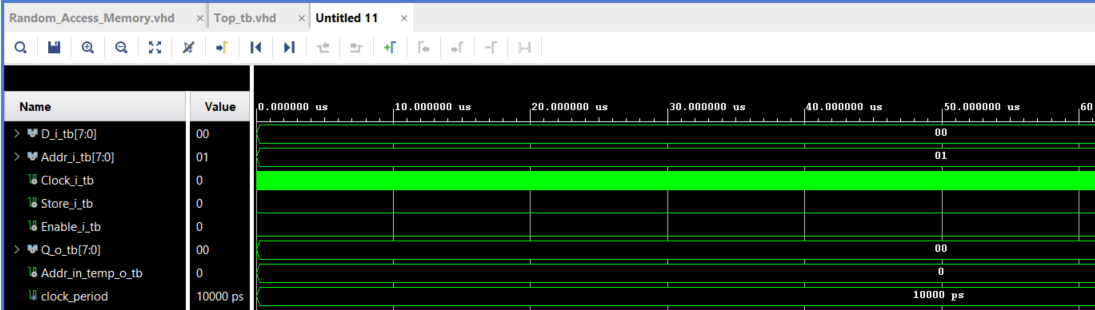
Simulation Waveform
2 Answers 2
There are some small problems in your code: The output Addr_in_temp_o of Ramdom_Access_memory is not connected in your testbench. So the simulation always shows the value 0 (default value of integer) at the signal Addr_in_temp_o_tb. The clocked process in Random_Access_Memory is also sensitive to Addr_i which is not needed.
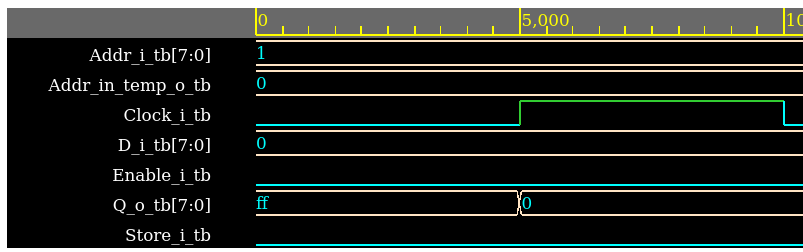
But the real problem is: In your testbench you permanently write (store=0) a 0 into the address 1 and you also read permanently (enable=0) from address 1. So of course you always read 0. If you zoom in at the time 0, you perhaps can see the value FF for 1 clock cycle at the read data output.
Assuming you are interested only in simulated behaviour, since this initialization may not be synthesizeable, both types work:
signal RAM : RAM_ARRAY := ( others => (others => '1') );
signal RAM : RAM_ARRAY := ( others => "11111111" );
But, since you are not stopping the simulation, you don't see the first and only cycle when the 0xFF appears. To stop it, you could do the following:
Clock_Gen : Process
begin
 Clock_i_tb <= '0';
 wait for clock_period/2;
 Clock_i_tb <= '1';
 wait for clock_period/2;
 wait; -- Stop the simulation
end process;
if(Store_i = '0') thencheck for a1instead of a0? \$\endgroup\$