After a few tutorials, I'm writing my first VHDL entity of my own.
Given an input signal and a 50MHz clock, it's supposed to emit a 6-clock-pulse strobe (120μs) when the time between two transitions in the input signal is longer than 21 clock pulses (420μs), and emit nothing if the transitions are shorter.
It revolves around a 5-bit binary counter. At each clock pulse it samples the input signal and compares it with the previous sample to see if a transition has occurred. If no change, keep counting; otherwise, set the strobe high if the counter reached 21, and reset it in any case. Also reset the strobe at the sixth clock pulse after the last transition.
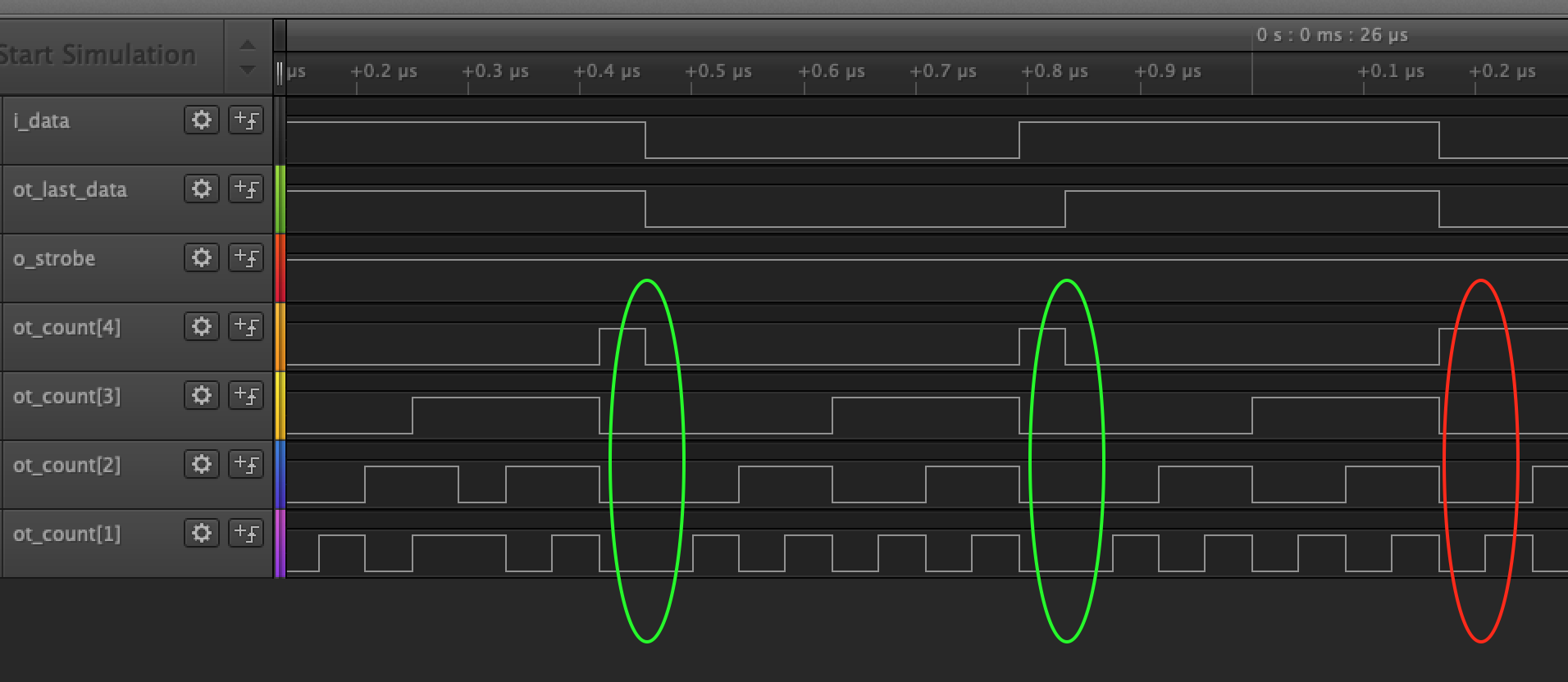
While it works fine in ModelSim (using a stimulus taken from a real-world signal), IRL it often fails to recognize a transition, causing problems downstream. Here's a screenshot from the logic analyzer:
Here the pulses are shorter, and the counter is supposed to reset at 16-17 (note the bit 0 isn't shown, it switches too quickly for my 24Msps logic analyzer). I'd expect the counter ot_count to reset at every transition of i_data/ot_last_data, but sometimes it keeps counting.
Here's the code:
library ieee;
use ieee.std_logic_1164.all;
use ieee.std_logic_unsigned.all;
use ieee.numeric_std.all;
entity SpdifAmp is
 port(
 i_clock: in std_logic;
 i_data: in std_logic;
 o_strobe: out std_logic;
 ot_last_data: out std_logic;
 ot_count: out std_logic_vector (4 downto 0)
 );
end SpdifAmp;
architecture rtl of SpdifAmp is
 signal r_last_data : std_logic := '0';
 signal r_count : std_logic_vector (4 downto 0);
 signal r_strobe : std_logic := '0';
 constant c_zeros : std_logic_vector(r_count'range) := (others => '0');
begin
 SyncFinder : process(i_clock, i_data, r_strobe, r_count, r_last_data)
 begin
 if rising_edge(i_clock) then
 if i_data = r_last_data then
 r_count <= r_count + 1;
 if r_count = 6 then
 r_strobe <= '0';
 end if;
 else
 if r_count > 21 then
 r_strobe <= '1';
 end if;
 r_count <= c_zeros;
 r_last_data <= i_data;
 end if;
 end if;
 o_strobe <= not r_strobe;
 ot_last_data <= r_last_data;
 ot_count <= r_count;
 end process SyncFinder;
end rtl;
Seems like the if i_data = r_last_data then is under some race condition; being new to VHDL I don't understand what's wrong and how to fix this.
-
\$\begingroup\$ Beware of line inductance on 50MHz clock and radiated noise. Attempt to dampen it with say 100 ~220 Ohm terminator and see if any effects. \$\endgroup\$Tony Stewart EE since 1975– Tony Stewart EE since 19752020年05月17日 00:18:27 +00:00Commented May 17, 2020 at 0:18
1 Answer 1
Incoming signals that are asynchronous to your FPGA must be synchronized to your FPGA's clock domain by running it through a chain of at least two flip flops before using it with any synchronous logic. Or else nothing guarantees that the incoming asynchronous edge does not land on an FPGA clock edge resulting in metstability. The chain of flip-flops reduces the chances of metastability so that they are vanishingly small. This does add latency.
That's why it works in your simulation but not in real life.
I recommend you write a separate component dedicated to synchronizing. Also one that outputs a single clock enable pulse for edge detection. Then connects those as components to or within your other entities that youy write. They come up a lot and it saves time and keeps your entities clean.
My edge detector component has an clock enable output for both rising and falling edges and my synchronizing component lets me select how many flip flop chains I want.