As a first step towards learning VHDL and using FPGAs, I want to implement a simple UART transmitter which only transmits a constant bit-sequence according to the UART protocol with 9600 8N1 configuration.
I'm using a Altera Cyclone II EP2C5T144C8N board which has a 50MHz clock.
The transmitter is supposed to cycle through all the bits in the bitstring repeatedely on every rising clock of the 9600 Hz clock, which is generated by a counter beforehand.
The VHDL code is as follows:
uart_test.vhdl:
library IEEE;
use IEEE.STD_LOGIC_1164.ALL;
use IEEE.numeric_std.ALL;
use IEEE.std_logic_unsigned.ALL;
entity UART_TX is
 Port (clk9600: in std_logic; -- 9600 Hz clock
 TX : out std_logic -- TX pin
 );
end UART_TX;
architecture Behavioral of UART_TX is
-- dummy data
-- idle (1) for a 3 cycles, start bit (1 to 0 transition), 8 bits of data ('A'), stop bit (=1)
constant bits_to_transmit : std_logic_vector (0 to 12) := "1110100000101";
signal current_bit : std_logic :='1';
signal current_index: integer range 0 to 12 := 0;
begin
 process (clk9600) -- on every clock tick
 begin
 if rising_edge(clk9600) then
 -- grab the current bit (in first iteration current_index = 0)
 current_bit <= bits_to_transmit(current_index);
 -- increment index by one (automatically overflows back to 0)
 current_index <= current_index + 1;
 end if;
 end process;
 -- assign TX the current bit
 TX <= current_bit;
end Behavioral;
Top level entity blinky.vhdl:
library IEEE;
use IEEE.STD_LOGIC_1164.ALL;
use IEEE.numeric_std.ALL;
use IEEE.std_logic_unsigned.ALL;
use WORK.all;
entity blinky is
 Port (clock50: in std_logic; -- internal 50MHz clock
 TX_out : out std_logic; -- transmit pin
 clock9600: out std_logic -- 9600Hz clock out for debug
 );
end blinky;
architecture Behavioral of blinky is
-- counter for frequency dividing 50 MHz to 9600 (Clk period is 50000000 / 9600 / 2 = ~2604)
signal c : integer range 0 to 2604 := 0;
signal internal_clk9600 : std_logic := '0';
-- component prototypes
component UART_TX is
 Port (clk9600: in std_logic; -- 9600 Hz clock
 TX : out std_logic -- TX pin
 );
end component;
begin
 process begin
 wait until rising_edge(clock50);
 if (c<2604) then
 c <= c+1;
 else
 c <= 0;
 internal_clk9600 <= not internal_clk9600;
 end if;
 end process;
 clock9600 <= internal_clk9600;
 my_uart_tx : UART_TX port map (clk9600=>internal_clk9600, TX=>TX_out);
end Behavioral;
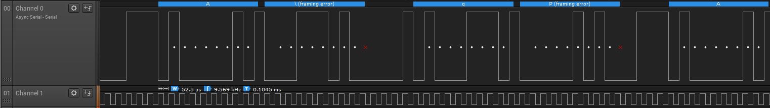
The output on the TX pin is not what I expect. It transmits the 'A', then 3 garbage characters, then 'A' again. I captured the signals with a logic analyzer:
This does not correspond at all to the bit sequence I have programmed above. It seems that it inserts 0 bits after it has cycles through, which throws off the UART decoder? The 9600 clock looks however right.
Question: What is wrong with the code that causes this?
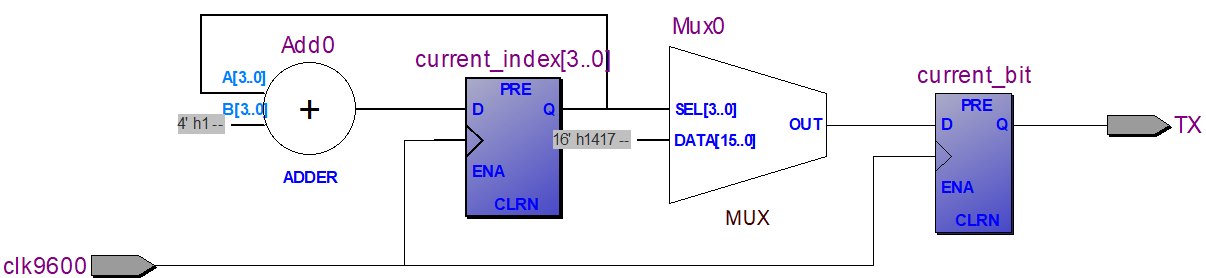
Side note: The RTL viewer shows a circuit which looks okay to me. rtl
1 Answer 1
I'm not a VHDL guru, but I think your comment
-- increment index by one (automatically overflows back to 0)
is misleading, and you have to explicitly reset the index after 12.
-
\$\begingroup\$ Even though I constrain it by saying
signal current_index: integer range 0 to 12 := 0;? Ok, will try anyways. \$\endgroup\$Maximilian Gerhardt– Maximilian Gerhardt2018年03月10日 00:41:25 +00:00Commented Mar 10, 2018 at 0:41 -
\$\begingroup\$ That was indeed it, but why? (new code pastebin.com/SHYWmpfs). If you can elaborate on why my
range 0 to 12did not cause the signal to reset itself it 0 after being incremented, I'll accept it. \$\endgroup\$Maximilian Gerhardt– Maximilian Gerhardt2018年03月10日 00:51:07 +00:00Commented Mar 10, 2018 at 0:51 -
\$\begingroup\$ I believe the purpose of the range is to allow sufficient resources to be allocated (4 bits in this case) and there is no automatic synthesis of logic to constrain the signal. \$\endgroup\$Spehro 'speff' Pefhany– Spehro 'speff' Pefhany2018年03月10日 02:30:17 +00:00Commented Mar 10, 2018 at 2:30
-
\$\begingroup\$ An automatic constraint in synthesis wouldn't help simulation where current_index incremented to 13 would cause a bounds check error. The RTL Viewer output demonstrates the problem, current_index is a 4 bit binary counter (values 0 to 15) and the inputs to the mux for 13 to 15 are shown as '0' (16h1417 is 0001010000010111). Note integer c is checked for the end count in blinky. No modular integer types (introduced in Ada95, while VHDL is Ada83 based) nor do integers have bits. current_index is synthesized to a binary range large enough to contain it's value range. \$\endgroup\$user8352– user83522018年03月10日 13:00:27 +00:00Commented Mar 10, 2018 at 13:00