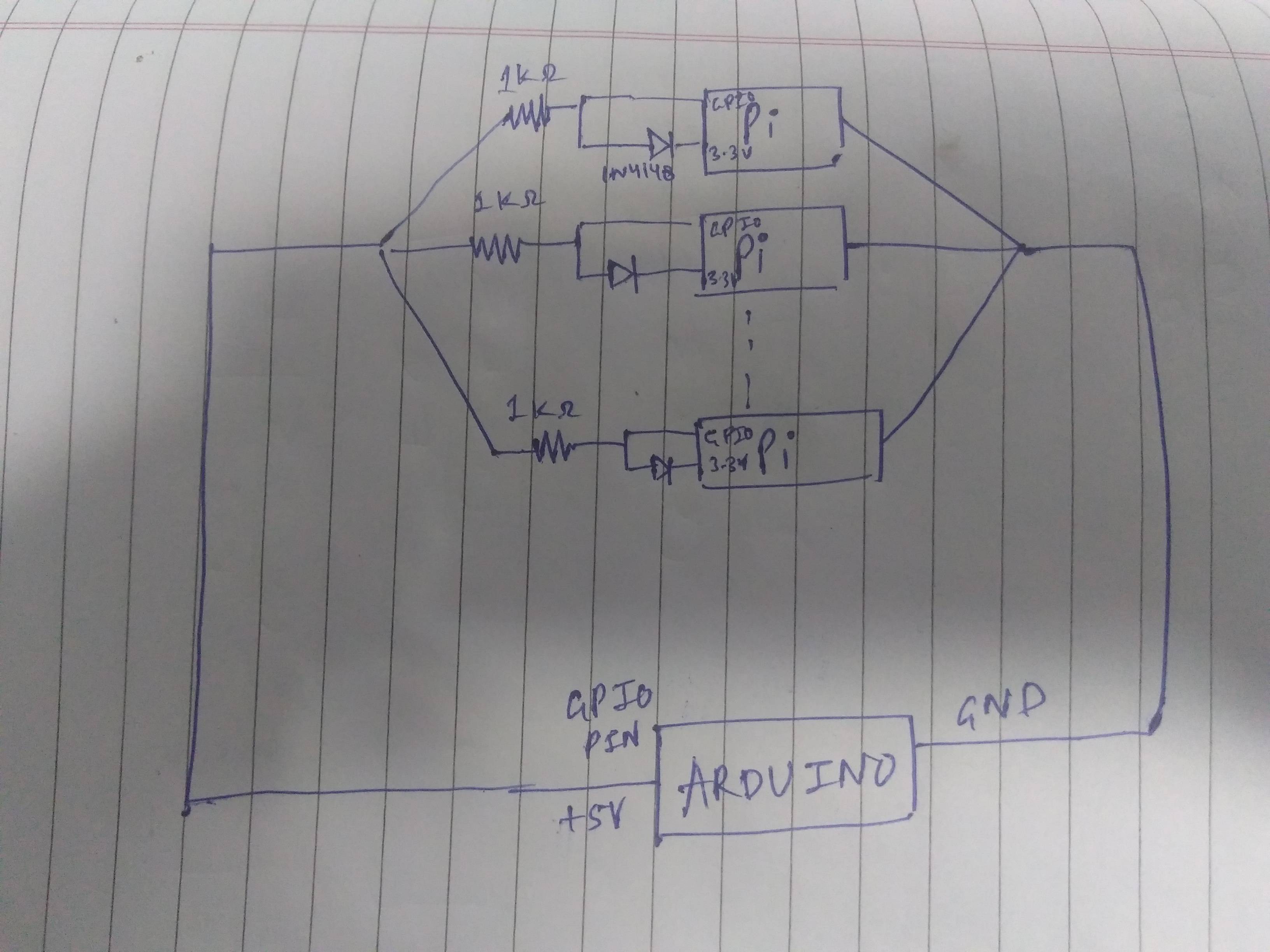
I am trying to send TTL pulse from single Arduino digital pin to 8 different Raspberry Pi simultaneously. For this I have connected 8 raspberry pi in parallel to arduino digital pin.
Since, Arduino runs at 5V and raspberry Pi at 3.3V, I am using a switching diode (1N4148) connected to 3.3V pin on pi as shown in the figure for droppping voltage levels.
Now here is my question, when I check for output voltage at Arduino it shows 0.2V rather than 5V which means that arduino pin is not able to drive all the pi as they are drawing a lot of current. Also another thing, when I start removing one pi at a time from circuit, the arduino starts working perfectly for 4 pi. As far I can think of this is mostly an issue related to not enough current to drive all pi.
How can I make this ciruit work?? I read up online that a voltage buffer say something like LM110, LM741 can be used to solve this issue. Is this the right direction to work on? Can something else be done?
-
\$\begingroup\$ An alternative would be to convert the 5V to 3.3V once instead of 8 times. \$\endgroup\$Wesley Lee– Wesley Lee2017年02月27日 12:46:43 +00:00Commented Feb 27, 2017 at 12:46
3 Answers 3
The diode circuit should work but not safe to parallel multiple loads to single drive. The voltage across the pi inputs will be diode drop plus 3.3 V (VCC of Pi). The current through the diode connected externally will be about 1.3 mA multiplied by 8 will give ~11 mA. Also, the input capacitance of all the Pi's inputs and 8 cables connected will make switching that current at high speed will get trouble with rise time and fall time too.
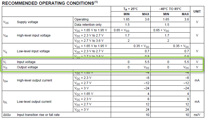
For your particular application, if you can buy one 74LVC245 buffer IC, please go ahead with below solution.
You can simply connect the Arduino single output to all the 8 inputs and derive 3.3 V level signals from the outputs. the advantage is that it is simple to use (Breadboard friendly) and easy to connect to.
The input voltage can be up to 5.5 V. Hence, it can accept the Arduino's input and drive the Pi's input easily.
-
\$\begingroup\$ I will test and update with my results soon. Thanks! \$\endgroup\$raj– raj2017年02月27日 12:58:05 +00:00Commented Feb 27, 2017 at 12:58
-
\$\begingroup\$ just a quick question,I am confused between buying one of these since I am not really good at it. Can you recommend which one will be suited for my purpose amongst these? Thanks for the help. goo.gl/TJPthV , goo.gl/7I4Ew0, goo.gl/wTdNP1, goo.gl/w7cqOv, goo.gl/WE3R70 \$\endgroup\$raj– raj2017年03月02日 14:10:35 +00:00Commented Mar 2, 2017 at 14:10
-
\$\begingroup\$ The first link I checked was alright. goo.gl/TJPthV but, wait a minutr3. If you do not have the IC AND have a NPN transistor AND have a requirement to drive only in one direction always. Then why not try the solution from Dmitry below. I suggest you to try it. \$\endgroup\$User323693– User3236932017年03月02日 14:16:17 +00:00Commented Mar 2, 2017 at 14:16
-
\$\begingroup\$ Sorry, the one I mentioned on the link isn't breadboard friendly. Let me search the one for you. \$\endgroup\$User323693– User3236932017年03月02日 14:23:36 +00:00Commented Mar 2, 2017 at 14:23
-
\$\begingroup\$ Is it alright to buy this one in SOT23 package?ti.com/general/docs/lit/… advantage is that the chip has only 6 pins and for this application sufficient . \$\endgroup\$User323693– User3236932017年03月02日 14:33:12 +00:00Commented Mar 2, 2017 at 14:33
The more classic diode level shift circuit is this one
schematic
simulate this circuit – Schematic created using CircuitLab
The output of that can drive as many inputs as you like.
While your ad-hoc solution with diodes might work, you might as well use a proper voltage level converter:
schematic
simulate this circuit – Schematic created using CircuitLab
(ground connection between Arduino and all RPi boards is assumed)
Since you drive all 8 RPi boards with the same signal, you should convert the voltage level only once, then distribute that signal to all the RPi boards.