I wrote a code to generate 1kHz Phase and frequency correct PWM signal from Arduino mega 2560 using timer 4. When I try the code with fast PWM mode it works perfectly. But phase correct mode didn't provide the expected outcome. What is wrong with my code?
unsigned int b=7999;
void setup() {
pinMode(6,OUTPUT);
pinMode(7,OUTPUT);
TCCR4A=0;
TCCR4B=0;
//Timer 1 1kHz mode 8: phase and frequency correct pwm oc1a non inverting
TCCR4A=(1<<COM4A1)|(0<<COM4A0)|(0<<WGM41) ;//| (0<<WGM40)
TCCR4B=(1<<WGM43)|(0<<WGM42);//
ICR4=b;
OCR4A=int(b*1/5);
TCCR4B|=(1<<CS10);
TIMSK4 |=(1<<OCIE4A);
}
void loop() {
 }
ISR(TIMER_COMPA_vect){
 }
The output of the code for different duty cycles are as below Duty cycle:0.2 (OCR4A=b/5) enter image description here
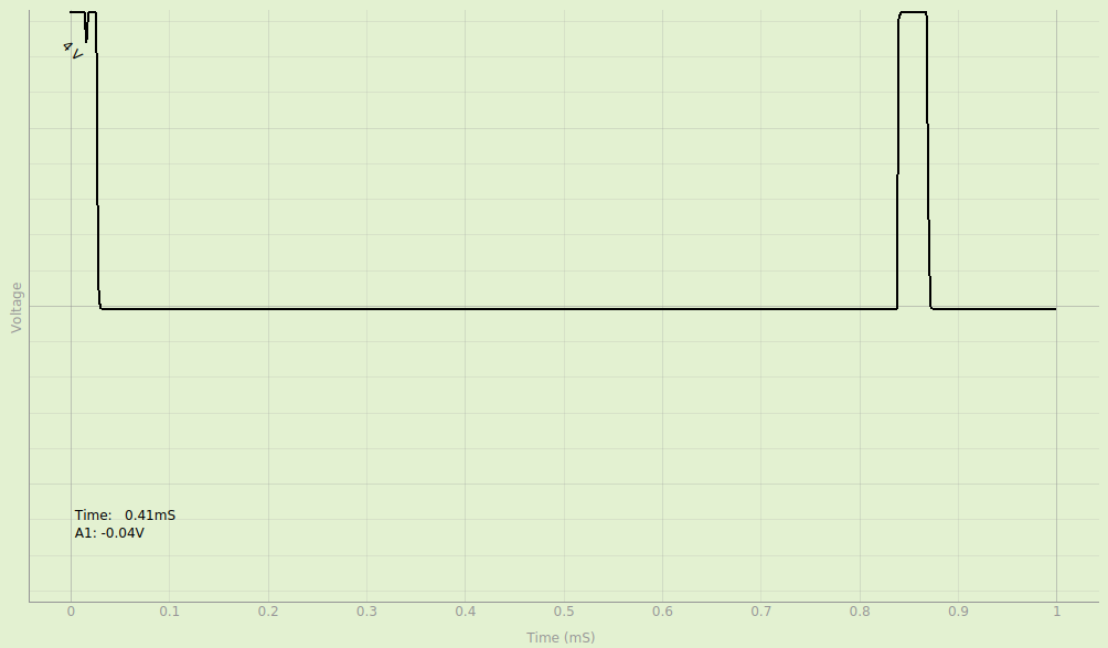
Duty cycle:0.2 (OCR4A=b/2)enter image description here
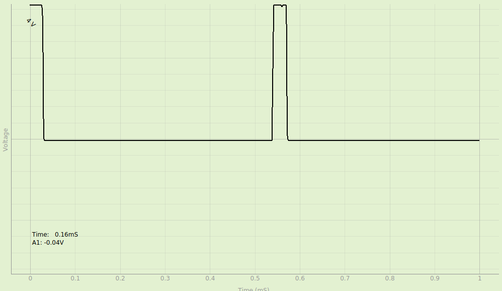
VE7JRO
2,51519 gold badges27 silver badges29 bronze badges
asked Jul 5, 2019 at 5:47
-
see the diagrams for pwm timing in the datasheetJuraj– Juraj ♦2019年07月05日 06:36:38 +00:00Commented Jul 5, 2019 at 6:36
-
Can you please explain what is wrongVivek Vijayan– Vivek Vijayan2019年07月05日 06:40:08 +00:00Commented Jul 5, 2019 at 6:40
-
in phase correct pwm the counter counts up and then down and so it matches the compare register twice in one period. first while counting up a second match while counting down. the pin changes state on both matchesJuraj– Juraj ♦2019年07月05日 08:04:18 +00:00Commented Jul 5, 2019 at 8:04
-
That's what I need. But it's clear from the wave form that the pin trigger while down counting and resets immediately as a glitchVivek Vijayan– Vivek Vijayan2019年07月05日 08:36:39 +00:00Commented Jul 5, 2019 at 8:36
1 Answer 1
You wrote:
TIMSK4 |= (1<<OCIE4A);
and then never defined ISR(TIMER4_COMPA_vect). As soon as you get a
compare match, you get a bad interrupt, which defaults to resetting your
program and restarting again from reset vector.
answered Jul 5, 2019 at 10:08
-
When I added interrupt service routine (ISR(TIMER4_COMPA_vect)) the output waveform acts exactly like fast PWM. It does not provide phase correct waveVivek Vijayan– Vivek Vijayan2019年07月05日 13:47:26 +00:00Commented Jul 5, 2019 at 13:47
-
@VivekVijayan: Do you get the expected frequency? If so, how do you tell it is not phase correct?Edgar Bonet– Edgar Bonet2019年07月05日 14:19:24 +00:00Commented Jul 5, 2019 at 14:19
-
@Edger Bonet: I am getting the expected frequency. But when I observe the waveform all the waves with different duty cycle starts from the same point. I believe in phase correct pwm mode the OCnA or OCnB pins are set during upcounting. So I could expect different starting points(in time) for waves with different duty cyclesVivek Vijayan– Vivek Vijayan2019年07月05日 14:42:40 +00:00Commented Jul 5, 2019 at 14:42
-
@VivekVijayan: You would not get 1 kHz in fast PWM mode. Re "different starting points (in time)": What is your time reference for defining the starting points? Are you using an oscilloscope? If so, how did you configure its trigger?Edgar Bonet– Edgar Bonet2019年07月05日 15:47:05 +00:00Commented Jul 5, 2019 at 15:47
-
1@VivekVijayan: Your phase correct waveform is fine. It looks wrong to you only because you don't understand how your DSO sets its time axis.Edgar Bonet– Edgar Bonet2019年07月05日 16:47:04 +00:00Commented Jul 5, 2019 at 16:47