The following question is based on the Arduino Pro Mini (8MHz, 3.3V)
I'm in process of developing (yet another) LED strip driver shield. For that I wrote a simple control loop, that adjusts the channel brightness (PWM duty cycle) to a given target value with a smooth transition.
For testing purposes I configured Timer1 with a 0.5Hz interval to randomly assign new target values. This works almost as intended. When watching the values you can see the constant value periods and completely random, fast changing periods in between (picture generated with Arduino built-in plot). The curved, rather smooth lines are the PWM outputs following the target value (that part is confirmed to work): enter image description here
The relevant code responsible for the changing of the target value is
ISR(TIMER1_COMPA_vect) //timer1 interrupt 0.5Hz
{
 for(auto it = 0; it < 4; ++it)
 channel_target[it] = random(0, 255); // assign a random value between 0..255 (max for pwm)
}
My assumption is, that the ISR is called very fast in the fuzzy intervals but since I havn't done much with arduinos yet, I'm not familiar on what kind of background functions might interfere with that.
For completeness the full code:
double channel[4];
uint8_t channel_target[4];
const double channel_k_p[4] = { 0.001, 0.001, 0.001, 0.001 };
const double channel_k_i[4] = { 0.01, 0.01, 0.01, 0.01 };
double err;
const uint8_t led_pins[4] = { 3, 5, 6, 9 };
char serial_buffer[100];
void setup()
{
 Serial.begin(9600);
 for(auto it = 0; it < 4; ++it)
 channel[it] = 0;
 for(auto it = 0; it < 4; ++it)
 {
 pinMode(led_pins[it], OUTPUT); // sets the pin as output
 analogWrite(led_pins[it], 0);
 }
 cli();//stop interrupts
 TCCR1A = 0;// set entire TCCR1A register to 0
 TCCR1B = 0;// same for TCCR1B
 TCNT1 = 0;//initialize counter value to 0
 // set compare match register for 1hz increments
 OCR1A = 15624;// = (8*10^6) / (0.5*1024) - 1 (must be <65536)
 // turn on CTC mode
 TCCR1B |= (1 << WGM12);
 // Set CS10 and CS12 bits for 1024 prescaler
 TCCR1B |= (1 << CS12) | (1 << CS10);
 // enable timer compare interrupt
 TIMSK1 |= (1 << OCIE1A);
 //set timer2 interrupt at 500Hz
 TCCR2A = 0;// set entire TCCR2A register to 0
 TCCR2B = 0;// same for TCCR2B
 TCNT2 = 0;//initialize counter value to 0
 // set compare match register for 8khz increments
 OCR2A = 248;// = (8*10^6) / (500*64) - 1 (must be <256)
 // turn on CTC mode
 TCCR2A |= (1 << WGM21);
 // Set CS21 bit for 64 prescaler
 TCCR2B |= (1 << CS21) | (1 << CS20);
 // enable timer compare interrupt
 TIMSK2 |= (1 << OCIE2A);
 sei(); // reactivate interrupts
 randomSeed(analogRead(0));
}
void loop()
{
 for(auto it = 0; it < 4; ++it)
 {
 sprintf(serial_buffer, "%d ", channel_target[it]);
 Serial.write(serial_buffer);
 }
 for(auto it = 0; it < 4; ++it)
 {
 sprintf(serial_buffer, "%d ", round(channel[it]));
 Serial.write(serial_buffer);
 }
 Serial.write("\n");
 delay(100);
}
ISR(TIMER2_COMPA_vect) // timer2 interrupt at 1kHz
{
 // ******************************
 // Channel brightness control loop
 for(auto it = 0; it < 4; ++it)
 {
 err = channel_target[it] - channel[it];
 channel[it] += err * channel_k_p[it]; // proportional
 channel[it] -= err * 0.002 * channel_k_p[it]; // integral
 if(channel[it] > 255)
 channel[it] = 255;
 analogWrite(led_pins[it], floor(channel[it]));
 }
}
ISR(TIMER1_COMPA_vect) //timer1 interrupt 0.5Hz
{
 for(auto it = 0; it < 4; ++it)
 channel_target[it] = random(0, 255); // assign a random value between 0..255 (max for pwm)
}
-
Setting the timer register to 0 as the first ISR instruction or deactivating interrupts with cli(); /* ISR code */ sei(); does not help.Patrick– Patrick2018年07月27日 10:52:30 +00:00Commented Jul 27, 2018 at 10:52
-
Arduino code doesn't give you an easy control over all interrupts. In this case there is a possibility that Serial.write makes mess with interrupts. I would recommend to take a closer look at this. Also delay() is based on some interrupts.smajli– smajli2018年07月27日 10:53:58 +00:00Commented Jul 27, 2018 at 10:53
1 Answer 1
The analogWrite() function generates a PWM output signal using a
hardware timer. Output on pin 3 is driven by timer 2, whereas
output on pin 9 is driven by timer 1. Here, you are trying to
use these timers for PWM generation and for your own code timing at
the same time. This cannot work. Either you let the Arduino core library
use the timers for analogWrite(), or you take them for you, but not
both.
The solution to your problem is very simple. Nothing in your code really requires a timer to start with. You can handle both the brightness control loop and the value changes using the technique of the Blink Without Delay Arduino tutorial:
const uint32_t TARGET_CHANGE_PERIOD = 500000;
const uint32_t BRIGHTNESS_UPDATE_PERIOD = 1000;
void loop()
{
 uint32_t now = micros();
 static uint32_t last_target_change;
 if (now - last_target_change >= TARGET_CHANGE_PERIOD) {
 last_target_change += TARGET_CHANGE_PERIOD;
 // Change the brightness targets.
 }
 static uint32_t last_brightness_update;
 if (now - last_brightness_update >= BRIGHTNESS_UPDATE_PERIOD) {
 last_brightness_update += BRIGHTNESS_UPDATE_PERIOD;
 // Update the channel brightnesses.
 }
}
-
Thank you very much. Is there a documentation for the timer usage somewhere (which timer is used by the arduino system for what)? I knew there are some parts of the arduino system that use various hardware timer, but except the dealy()/millis() <-> timer0 connection I couln't find any information in that regard.Patrick– Patrick2018年07月27日 13:41:34 +00:00Commented Jul 27, 2018 at 13:41
-
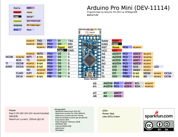
@Patrick: The only authoritative info is probably the source code. It shows timer 0 is used for timekeeping and all three timers for PWM. To match pins to timers, see for example this pinout diagram. Every PWM-capable pin has a label "OCnx", where n is the timer number (0 – 2) and x is the timer's channel (A or B).Edgar Bonet– Edgar Bonet2018年07月27日 14:43:34 +00:00Commented Jul 27, 2018 at 14:43
Explore related questions
See similar questions with these tags.