Regarding my program, it is a program that does some calculations and then outputs a voltage based on the result using analogWrite function. However my problem is that I had done my programming based on a misconception that analogWrite function via PWM does output an analog voltage, where in fact it only "simulates" the analog voltage instead.
Here are the relevant parts of my code :
int pwmOutput = 11;
int pwm = 0;
void compareNewOldVoltageYes(void)
{
 if(pv_Vnew > pv_Vold && pwm != 255)
 {
 ++pwm; //increasing value
 }
 else if(pwm != 0)
 {
 --pwm; //decreasing
 }
}
void compareNewOldVoltageNo(void)
{
 if(pv_Vnew > pv_Vold && pwm != 0)
 {
 --pwm;
 }
 else if(pwm != 255)
 {
 ++pwm;
 }
}
void loop()
{
 reading();
 PowerCalculation();
 if(pv_NewP > pv_OldP)
 {
 compareNewOldVoltageYes();
 }
 else
 {
 compareNewOldVoltageNo();
 }
 analogWrite(pwmOutput, pwm); //analogWrite
 float displayPWMvolt = pwm * 0.0196;
 Serial.print("Output Voltage: ");
 Serial.print(displayPWMvolt);
 Serial.println(" V");
 pv_OldP = pv_NewP;
 Serial.print("Previous Power: ");
 Serial.print(pv_OldP);
 Serial.println(" W");
}
As for the circuitry, output pin 11 is being connected to a 1 ohm resistor and then to GND. (Where I measured the voltage) I am using Arduino Uno board.
UPDATE:
As said in the comments by @DatHa, pwm does not output voltage. Is there a way to output voltage as said, without changing the board?
-
1P.S. Analog write uses PWM and it DOES NOT produce an analog voltage.Dat Ha– Dat Ha2016年11月28日 01:30:19 +00:00Commented Nov 28, 2016 at 1:30
-
@DatHa does that mean it cannot be done this way? Is there another function to output analog voltage?bytk– bytk2016年11月28日 01:32:38 +00:00Commented Nov 28, 2016 at 1:32
-
See @Russell answer on arduino.stackexchange.com/questions/10041/…duck– duck2016年11月28日 01:34:54 +00:00Commented Nov 28, 2016 at 1:34
-
@dpw I don't think that works as my program has to connect to an electronic load via its external programming port and control it using 0-5V.bytk– bytk2016年11月28日 01:43:01 +00:00Commented Nov 28, 2016 at 1:43
-
PWM outputs a specific voltage, or I'm a pirate in the year of our Lord 1734. You can't go above an 8-bit value, and there's always some inaccuracy in reading it.user400344– user4003442016年11月29日 22:12:21 +00:00Commented Nov 29, 2016 at 22:12
6 Answers 6
You basically have three options:
- Switch to an Arduino Due which has a built-in DAC which outputs a real voltage.
- Add an external DAC chip (such as the MCP4821/2) to create the voltage for you
- Use a low-pass filter (R-C network) on a PWM pin.
Of the three options I usually use an MCP4822 since it gives the best results and doesn't cost as much as using a Due.
-
Thank you. Option 2 sounds really good, but due to time constrains, I went ahead with Option 3 and got the results I wanted.bytk– bytk2016年11月28日 13:48:59 +00:00Commented Nov 28, 2016 at 13:48
-
1or use an R-2R ladder as a "poor man's DAC"Andre Holzner– Andre Holzner2016年11月28日 16:54:42 +00:00Commented Nov 28, 2016 at 16:54
-
1@AndreHolzner I count an R-2R ladder the same as a DAC chip but with too many wires to make it practical on your average Arduino.Majenko– Majenko2016年11月30日 00:35:49 +00:00Commented Nov 30, 2016 at 0:35
-
@Majenko I just wanted to add that there exist "digital potentiometers" or "digipots" that are pretty much R-2R ladders inside a DIP-8 chip. They are cheaper then DACs. (For example X9C103)Filip Franik– Filip Franik2019年03月28日 07:55:06 +00:00Commented Mar 28, 2019 at 7:55
-
1@FilipFranik Except they're not R-2R ladders. They're just a chain of resistors with a FET connected to each connection between resistors. There is only R. Many Rs all the same. Yes, if you write it up with the two ends of the potentiometer to VCC and GND you get kind of a DAC, but it suffers the same kind of impedance problems a real potentiometer does. It provides a pair of resistances, whereas a DAC provides a voltage.Majenko– Majenko2019年03月28日 12:27:53 +00:00Commented Mar 28, 2019 at 12:27
At 5V, a 1 ohm resistor will try to sink 1A and far exceed the 40mA specs. Please use at least a 5/0.040=125 ohm resistor to protect your pin. And if you put the a capacitor between your resistor and ground, the RC circuit of the capacitor will smooth out the PWM into an analog voltage.
Please try the suggested @russell answer with a 47K resistor and 1uF capacitor, you will get an analog voltage at the junction to use with your electronic load.
As far as I know Arduinos have ADC (Analog to Digital Converters) but do not have any DAC (Digital to Analog Converters). So you can not output a set voltage from any pins based on a digital value.
-
3The ARM based Arduinos usually have at least one DAC channel.KIIV– KIIV2016年11月28日 07:54:10 +00:00Commented Nov 28, 2016 at 7:54
There is no direct way.
In addition to @Majenko
Alternative way: you can use H bridge like L293d to provide continuous level. Many diy inverter circuits are useing this technique.
http://www.instructables.com/id/How-to-Make-an-Inverter-Using-ARDUINO/?ALLSTEPS
NO.. There is no way to get an analog voltage from the Arduino. The best that you can do is to use Arduino as a Buck Voltage converter in linear or boost mode using a voltage regulator, inductor and the mosfet transistor. You will also might need to use a Mega or Dulorme which provide a PWM frequency other that the standard 50o Hz.
Best luck
I wondered if this would give a more stable output.
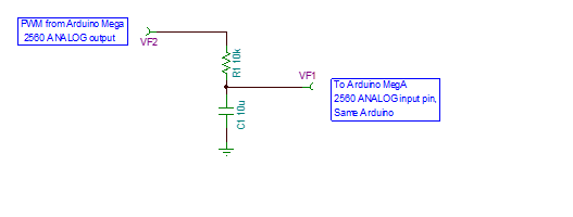
-
You need to add an R in parallel with C1 to discharge C1.MatsK– MatsK2020年08月23日 14:24:33 +00:00Commented Aug 23, 2020 at 14:24
Explore related questions
See similar questions with these tags.