I am trying to do voltage measurement using Arduino. I am using a voltage divider circuit to reduce the voltage to less than 5V. I measured the voltage on the 5V pin of Arduino and found out that its 4.279 V (I am powering through USB). So, I am doing following calculations for voltage measurement:
int data1 = analogRead(A0);
float data2 = data1 * (4.279/1023.0);
float volts = data2 * (10 + 2.2)/2.2; //R1=10k , R2=2.2k
Serial.println(volts);
if(volts > 12.00)
{
 digitalWrite(6,HIGH);
}
if(volts < 12.00)
{
 digitalWrite(6,LOW);
}
So I am getting exact values of voltage. Now I have put a condition like if volt is greater than 12V, turn on an output, else turn off the output. For output, I have a transistor and mosfet connected. As soon as the voltage increases above 12V, output get on but the problem is that when the output is on, Arduino displays wrong values. Like if the voltage is 12.3, it shows 13.6.
I looked it into more and found out that the voltage at 5V pin of Arduino (4.279) gets reduced to 3.865 and due to which calculation goes wrong and it displays wrong values of voltage.
Is there anything which I am doing wrong? Is there any function or keyword in Arduino libraries which can tell us the voltage or is there any way through which we can measure it? I tried putting the 5V pin to analog pins to read it and convert it into volts but again for this we need a reference voltage. I hope I have explained the question clearly.
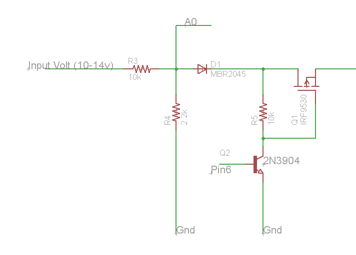
Schematic
A0 is the analog pin and PIN6 is digital output of arduino
-
Full schematic and code please.Majenko– Majenko2016年09月07日 13:15:50 +00:00Commented Sep 7, 2016 at 13:15
-
@Majenko I have updated the code and schematic.S Andrew– S Andrew2016年09月07日 13:20:46 +00:00Commented Sep 7, 2016 at 13:20
-
I thought so. You have no base resistor on your BJT. That's causing a brownout.Majenko– Majenko2016年09月07日 13:22:00 +00:00Commented Sep 7, 2016 at 13:22
-
@Majenko base resistor. I didn't get you. Do you mean resistor on base. Can you please describe itS Andrew– S Andrew2016年09月07日 13:24:19 +00:00Commented Sep 7, 2016 at 13:24
-
A small resistor between pin 6 and the base of the resistor to limit the current that can flow through the base. Since you are only switching a MOSFET with it the actual value doesn't matter that much - maybe around 1KΩ should be OK.Majenko– Majenko2016年09月07日 14:23:48 +00:00Commented Sep 7, 2016 at 14:23
1 Answer 1
It would appear that the wrong A/D reading is due to the reduced +5V output. The A/D reference is powered by the input to the computer chip. The big question is what is causing the voltage drop. Are you powering something else from the USB supply when the FET is turned on? Bottom line is that you cannot expect the A/D to read the same voltage when the voltage input to the computer chip is changed.
-
I have connected my arduino using USB and when nothing is connected and blinky program is running, it shows 4.279v instead of 5v. In my project I am planning to use only
ATMEGA328Pinstead of the complete arduino so in that case I will giving it the full 5v power, so may be at that time it will show 5v.S Andrew– S Andrew2016年09月08日 04:19:57 +00:00Commented Sep 8, 2016 at 4:19