Data modeling is not yet covered by the Unified Modeling Language (UML), even though persistence-related issues are clearly an important aspect of object-oriented software initiatives. For many years I have argued that the UML needs a data model (first in Building Object Applications that Work in 1997 and most recently in Refactoring Databases) and have vacillated between various ways that it should be done. Other methodologists have argued the same (Naiburg and Maksimchuk 2001, Muller 1999) because they recognize the clear need to extend the UML. Unfortunately, we have all come up with slightly different modeling notations, a problem that the UML is supposed to address, if my memory serves me correctly. This page summarizes an unofficial profile for a UML data model that is based on UML Class Diagrams. I apply this profile on this site and in the books Agile Database Techniques, The Object Primer 3rd Edition, and Refactoring Databases.
First some important definitions:
This profile follows the strategy of separating core notation, the 20% that you are likely to use in practice, from supplementary notation that isn’t as common although still needed in some situations. The notation presented here isn’t perfect but I truly believe that it’s the best source available to you today. Nor is this profile complete – for the most part it focuses on the physical modeling of a relational database, although it does cover other aspects of data modeling as needed. This profile also strays into style issues, something that is not appropriate for a proper UML profile, issues that in my opinion are critical to successful modeling and this in my opinion is the best place to present them.
The type of model should be indicated either using the appropriate stereotype listed in Table 1 or simply as free form text in a UML note. In the case of a physical data model the type of storage mechanism should be indicated with one of the stereotypes listed in Table 2 .
Table 1. Stereotypes to Indicate Model Types (Core notation).
Table 2. Stereotypes for Various Persistent Storage Mechanisms (Supplementary Notation).
Tables, entities, and views are all modeled using class boxes, as you see in Figure 1 and Figure 2, and the appropriate stereotypes are listed in Table 3. Class boxes that appear on conceptual and logical data models are by definition entities so the stereotype is optional. Similarly, on a physical data model for a relational database it is assumed that any class box without a stereotype is a table. In Figure 2 you see that views have dependencies on the table structures.
Indices, shown in Figure 2, are also modeled using class boxes. They are optionally dependent on either the table for which they are an index or on the actual columns that make up the index (this is more accurate although can be more complex to depict when the index implements a composite key). In the model you see that IEmployee1 is dependent on the Employee_POID column whereas IEmployee2 is dependent on just the table, requiring you to list the columns for the index when you follow this style. As you can see the notation used for IEmployee2 is wordier but less clumsy – if you’re going to model indices this should your preference with respect to style issues.
Figure >1. A logical data model.
Figure 2. A physical data model for a relational database.
Table 3. Stereotypes for Classes.
Relationships are modeled using the notation for associations as you can see in Figure 1 and Figure 2. Standard multiplicity (e.g. 0..1, 1..*, and 2..5) notation may be applied, as can roles. Table 4 lists the potential stereotypes that you may apply to relationships, some of which have a common visual representation as well as a textual one. In general Iprefer to apply the visual stereotype over the textual one. The notation for qualifiers shouldn’t be used. Although it would be a valid option to model foreign keys in practice this often proves confusing when a single table is involved in many relationships.
Table 4. Stereotypes for Associations.
Data attributes on conceptual and logical data models, as well as columns on physical data models, are modeled using the standard attribute notation. It is optional to model the type of an attribute on a conceptual or logical data model although in practice this is often done. Stylistically, if the model is being used to model data requirements then the type should be indicated only when it is an actual requirement. For example, if a customer number must be alphanumeric then indicate it as such, otherwise if it is optional how this attribute is implemented then do not indicate the type.
Constraints, such as a column being not null, should be modeled using normal UML constraints (see below).
The notation for visibility shouldn’t be used – the assumption is that the data is publicly accessible. Although visibility symbols could be used to indicate the need to indicate access control this is better done using constraints.
An important issue which should be addressed for a column is whether it is a suggested source of information.
In my opinion, the modeling of keys is the the most complicated issue addressed by this profile. This is for several reasons:
As you can see in Figure 3 the notation for indicating keys can get quite complex. Minimally, you should mark the attribute or column with one of the key-oriented stereotypes in Table 5 . Although I would normally prefer stereotypes such as <<Primary Key>> over <<PK>>, I chose the abbreviated version because it reflects existing norms within the data community for indicating keys. Furthermore, because some columns can be involved with several keys the longer form of the stereotype would become cumbersome.
It is optional to model the detailed information pertaining to keys using UML tagged values (described in in Table 6). For example, in Figure 3 you see that:
In Figure 2 I indicated that Employee_POID is a surrogate key to provide an example of how to do this (had it been a natural key I would have applied the stereotype <<Natural>> instead). I generally prefer to indicate whether a key auto generated, natural, or surrogate in the documentation instead of on the diagrams – this is an option for you although in my opinion this sort of information adds to much clutter.
Figure 3. Modeling keys, constraints, and behaviors on a physical data model.
Table 5. Stereotypes for columns.
Table 6. Tagged values for modeling keys (supplementary notation).
key = AK-3 Only indicate this when the column is part of more than one key.
Most constraints (domain, column, table, and database) can be modeled using the UML’s Object Constraint Language (OCL) where appropriate. Examples of this are depicted in Figure 3, a domain constraint on the Order_Date is defined indicating that it must be later than January 1st 2000. A column constraint is also defined, the Customer_POID column mustn’t be null.
Table and database constraints (not shown) are be modeled the same way. For example Figure 3 depicts how a referential integrity (RI) constraint can be modeled between two tables using OCL notation. You see that when an order is deleted the order items should also be deleted. Although this implied by the fact that there is an aggregation relationship between the two tables the constraint makes this explicit. However, too many RI constraints can quickly clutter your diagrams, therefore supporting documentation for your database design might be a better option for this information so as not to clutter your diagrams – remember AM’s Depict Models Simply practice.
In Figure 2 the Salary table includes an access control constraint, only people in the HR department are allowed to access this information. Other examples in this diagram include the read only constraint on the VEmployee view and the ordered by constraint on Employee_Number in this view.
Triggers are modeled using the notation for methods(operations). In Figure 3 you see that the stereotype of <<Trigger>> was applied and tagged value of “after insert” and “before delete” were modeled to shown when the triggers would be fired. Stereotypes for methods are listed in Table 7.
Table 7. Stereotypes for methods.
Stored procedures should be modeled using a single class with the stereotype <<Stored Procedures>> as shown in Figure 3 and described in Table 3. This class lists the operation signatures of the stored procedures using the standard UML notation for operation signatures.
Although it is standard UML practice for stereotypes to be singular, in this case the plural form makes the most sense. The other alternative is to apply the stereotype <<Stored Procedure>> to each individual operation signature, something that would unnecessarily clutter the diagram.
Stylistically, the name of this class should either be the database or the name of the package within the database.
Many database management systems provide the ability to segregate your database into sections. In Oracle these sections are called tablespaces and other vendors call them partitions or data areas. Regardless of the term, you should use a standard UML package with a stereotype which reflects the terminology used by your database vendor (e.g. <<Tablespace>>, <<Partition>>, and so on).
For the sake of discussion in this section, a storage element is somewhere that you store data such as a column, table, or database and a database element is a storage element plus any non-storage elements such as stored procedures and views. A storage element potentially has suggested levels of access. For example, it may be the source of record and therefore it is highly suggested the people use it. It may be a copy of data from another source, a copy that may or may not be automatically replicated, or it may be deprecated and therefore it is suggested that the database element is not accessed at all. Table 8 provides suggestions for how to indicate this information and Figure 4 an example.
Table 8. Indicating suggested access.
There is far more to data modeling than what is covered by this profile. The approach that I’ve taken is to identify the type of information that you are likely to include on your diagrams, but this is only a subset of the information that you are likely to gather as you’re modeling. For example, logical data attribute information and descriptions of relationships can be important aspects of logical data models. Similarly replication info (e.g. which tables get replicated, how often, “¦), sizing information (average number of rows, growth rate, “¦), and archiving information can be critical aspects of your physical data model. Complex business rules are applicable to all types of models. Although this information is important, in my opinion it does not belong on your diagrams but instead in your documentation. Follow AM’s practice of Depict Models Simply by keeping this sort of information out of your diagrams.
If you feel there is something missing from this profile, and there definitely is, then let’s talk about it.
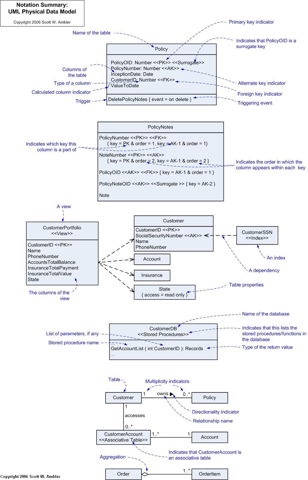
I originally developed Figure 4 for the inside cover of Refactoring Databases (which uses this notation throughout the book). I thought it might be a good reference diagram.
Figure 4. Notation summary.
[画像:UML Data Model Notation: Physical]
I firmly believe that the requirements for something should be identified before it is built. This is true of software-based systems and it should be true for UML profiles (even unofficial ones). This section presents a bulleted list of requirements from which I worked when putting this profile together. I have chosen to present the requirements last because I suspect most people are just interested in the profile itself and not how it came about.
If anyone intends to extend this profile I highly suggest that they start at the requirements just as I have. The high-level requirements are:
Need to support different types of models
Need to model entities and tables
Need to model the attributes and columns
Need to model relationships
Need to model keys
Need to model constraints and behaviors
Need to model source of record/access
We don’t.
If you find this information useful, or at least you think it is something that your colleagues may benefit from, please feel free to link to it. This will help to get the word out within the community. The more people that know about and use this notation the greater the chance that member of the OMG will take up and finish this work.
Suggested listing:
Title: A UML Profile for Data Modeling (Scott W. Ambler)
URL: AgileData.org/essays/umldatamodelingprofile.html
On November 2, 2003 I added this section to identify who has provided input into this profile.
Choose Your WoW! 2nd Edition
This book, Choose Your WoW! A Disciplined Agile Approach to Optimizing Your Way of Working (WoW) – Second Edition, is an indispensable guide for agile coaches and practitioners. It overviews key aspects of the Disciplined Agile® (DATM) tool kit. Hundreds of organizations around the world have already benefited from DA, which is the only comprehensive tool kit available for guidance on building high-performance agile teams and optimizing your WoW. As a hybrid of the leading agile, lean, and traditional approaches, DA provides hundreds of strategies to help you make better decisions within your agile teams, balancing self-organization with the realities and constraints of your unique enterprise context.
I also maintain an agile database books page which overviews many books you will find interesting.