Electric Motor Control
Electric Motor Control
10th Edition
ISBN: 9781133702818
Author: Herman
Publisher: CENGAGE L
expand_more
expand_more
format_list_bulleted
Bartleby Related Questions Icon
Related questions
Question
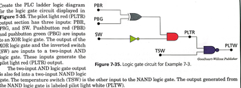
Transcribed Image Text:Create the PLC ladder logic diagram
for the logic gate circuit displayed in
Figure 7-35. The pilot light red (PLTR)
output section has three inputs: PBR,
PBG, and SW. Pushbutton red (PBR)
and pushbutton green (PBG) are inputs
to an XOR logic gate. The output of the
XOR logic gate and the inverted switch
SW) are inputs to a two-input AND
logic gate. These inputs generate the
pilot light red (PLTR) output.
The two-input AND logic gate output
is also fed into a two-input NAND logic
PBR
PBG
SW
TSW
PLTR
Figure 7-35. Logic gate circuit for Example 7-3.
PLTW
Goodheart-Willcox Publisher
gate. The temperature switch (TSW) is the other input to the NAND logic gate. The output generated from
the NAND logic gate is labeled pilot light white (PLTW).
Expert Solution
Check MarkThis question has been solved!
Explore an expertly crafted, step-by-step solution for a thorough understanding of key concepts.
bartleby
Step by stepSolved in 2 steps with 8 images
Knowledge Booster
Background pattern image
Recommended textbooks for you
- Text book imageText book imageElectricity for Refrigeration, Heating, and Air C...Mechanical EngineeringISBN:9781337399128Author:Russell E. SmithPublisher:Cengage LearningText book imageDelmar's Standard Textbook Of ElectricityElectrical EngineeringISBN:9781337900348Author:Stephen L. HermanPublisher:Cengage Learning
- Text book imageEBK ELECTRICAL WIRING RESIDENTIALElectrical EngineeringISBN:9781337516549Author:SimmonsPublisher:CENGAGE LEARNING - CONSIGNMENTText book imagePower System Analysis and Design (MindTap Course ...Electrical EngineeringISBN:9781305632134Author:J. Duncan Glover, Thomas Overbye, Mulukutla S. SarmaPublisher:Cengage Learning
Text book image
Text book image
Electricity for Refrigeration, Heating, and Air C...
Mechanical Engineering
ISBN:9781337399128
Author:Russell E. Smith
Publisher:Cengage Learning
Text book image
Delmar's Standard Textbook Of Electricity
Electrical Engineering
ISBN:9781337900348
Author:Stephen L. Herman
Publisher:Cengage Learning
Text book image
EBK ELECTRICAL WIRING RESIDENTIAL
Electrical Engineering
ISBN:9781337516549
Author:Simmons
Publisher:CENGAGE LEARNING - CONSIGNMENT
Text book image
Power System Analysis and Design (MindTap Course ...
Electrical Engineering
ISBN:9781305632134
Author:J. Duncan Glover, Thomas Overbye, Mulukutla S. Sarma
Publisher:Cengage Learning