Introductory Circuit Analysis (13th Edition)
Introductory Circuit Analysis (13th Edition)
13th Edition
ISBN: 9780133923605
Author: Robert L. Boylestad
Publisher: PEARSON
expand_more
expand_more
format_list_bulleted
Bartleby Related Questions Icon
Related questions
Question
Transcribed Image Text:+
2.
A
B
C
S
M
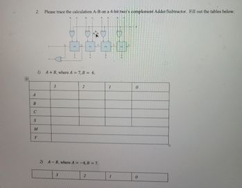
Please trace the calculation A-B on a 4-bit two's complement Adder/Subtractor. Fill out the tables below.
V
3
A1
FA
3
S2
G
1) A + B, where A = 7, B = 6.
B2
2
FA
S2
2
2) A-B, where A = -4, B = 7.
C2
FA
1
1
FA
S
0
0
Expert Solution
Check MarkThis question has been solved!
Explore an expertly crafted, step-by-step solution for a thorough understanding of key concepts.
bartleby
This is a popular solution
bartleby
Trending nowThis is a popular solution!
bartleby
Step by stepSolved in 3 steps with 6 images
Knowledge Booster
Background pattern image
Learn more about
Need a deep-dive on the concept behind this application? Look no further. Learn more about this topic, electrical-engineering and related others by exploring similar questions and additional content below.Similar questions
- Write the Boolean equation for the circuits of Figure Simplify the equations A B -Xarrow_forwardInput Output S BC D F Inputs: S1: (A) - S2: (B) - S3: (C) - S4: (D) Output: - F: L1 0000 0001 0010 0 011 1 00 01 11 10 A B00 0 100 0 101 0 1 10 0 111 1000 100 1 1010 1011 1100 1101 1110 1111 1 1 01 1 11 1 10 1 1arrow_forwardGiven the following image, which BCD codes which output will be high for the following input conditions on a BCD to decimal converter? BCD input code Do-02 ABCD=0010 ABCD=0101 06 ABCD=1001 Ő2 01arrow_forward
- 3) For the circuit shown in the following figure, Io - I3 are inputs to the 4:1 multiplexer. R (MSB) and S are control bits. The output Y can be represented by Answer: P 13 12 4:1 MUX B Io S1 So RS Y O PQ+PR+ P Q S OPQ+ PS + QRS O PQ R+PQR+ Q R S + PQRS OPQR+ PQRS + Q R S+PQ RSarrow_forwardFor the circuit shown below, Binary Number A = 1010 and Binary number B = 1110. What is the value at C 0D 0E 0F 1X 0please correct me if i am wrongarrow_forwardDesign a code converter that converts a decimal digit from BCD to excess-3 code, the input variables are organized as (A B C D) respectively with A is the MSB, the output variables are organized as (W XY Z) respectively with W is the MSB, put the invalid decimal numbers as don't care. W=A+BD+BC' W=A+BD+BC, W=A'+BD+BC W= BC'D'+B'D+B'Carrow_forward
- I need expert solution with circuit drawingarrow_forward2. The following figure shows the four-bit Subtractor. Your inputs for this combinational circuit are A = 2 and B = 7. What is the outputs S3, S2, S1, and S0? You have to show how to get the outputs by indicating each carry bit. (Note: You should show all the steps)arrow_forwardSolve step by step in digital format, please explain each step XXXXXXXXXXXXXXXXXXXXXXXXXXXXXXXXXXXX Determine (s) R(s) R(s) XXXXXXXXXXXXXXXXXXXXXXXXXXXXXXXXXXXXX Y(s) of the system represented as 1 1 s+5 s + 10arrow_forward
- This question is from my digital system class, i hope you can help me so i can studyarrow_forwardInstructions: USE KMAPS or LC to reduce the equations and or Generate the equations by inspection using SOPs'.arrow_forward3. The following figure shows the four-bit Adder-Subtractor. Your inputs for this combinational circuit are A = 8, B = 5 and M = 1. What is the outputs S3, S2, S1, and S0? You have to show how to get the outputs by indicating each carry bit. (Note: You should show all the steps to receive full credits)arrow_forward
arrow_back_ios
SEE MORE QUESTIONS
arrow_forward_ios
Recommended textbooks for you
- Text book imageIntroductory Circuit Analysis (13th Edition)Electrical EngineeringISBN:9780133923605Author:Robert L. BoylestadPublisher:PEARSONText book imageDelmar's Standard Textbook Of ElectricityElectrical EngineeringISBN:9781337900348Author:Stephen L. HermanPublisher:Cengage LearningText book imageProgrammable Logic ControllersElectrical EngineeringISBN:9780073373843Author:Frank D. PetruzellaPublisher:McGraw-Hill Education
- Text book imageFundamentals of Electric CircuitsElectrical EngineeringISBN:9780078028229Author:Charles K Alexander, Matthew SadikuPublisher:McGraw-Hill EducationText book imageElectric Circuits. (11th Edition)Electrical EngineeringISBN:9780134746968Author:James W. Nilsson, Susan RiedelPublisher:PEARSONText book imageEngineering ElectromagneticsElectrical EngineeringISBN:9780078028151Author:Hayt, William H. (william Hart), Jr, BUCK, John A.Publisher:Mcgraw-hill Education,
Text book image
Introductory Circuit Analysis (13th Edition)
Electrical Engineering
ISBN:9780133923605
Author:Robert L. Boylestad
Publisher:PEARSON
Text book image
Delmar's Standard Textbook Of Electricity
Electrical Engineering
ISBN:9781337900348
Author:Stephen L. Herman
Publisher:Cengage Learning
Text book image
Programmable Logic Controllers
Electrical Engineering
ISBN:9780073373843
Author:Frank D. Petruzella
Publisher:McGraw-Hill Education
Text book image
Fundamentals of Electric Circuits
Electrical Engineering
ISBN:9780078028229
Author:Charles K Alexander, Matthew Sadiku
Publisher:McGraw-Hill Education
Text book image
Electric Circuits. (11th Edition)
Electrical Engineering
ISBN:9780134746968
Author:James W. Nilsson, Susan Riedel
Publisher:PEARSON
Text book image
Engineering Electromagnetics
Electrical Engineering
ISBN:9780078028151
Author:Hayt, William H. (william Hart), Jr, BUCK, John A.
Publisher:Mcgraw-hill Education,