Introductory Circuit Analysis (13th Edition)
Introductory Circuit Analysis (13th Edition)
13th Edition
ISBN: 9780133923605
Author: Robert L. Boylestad
Publisher: PEARSON
expand_more
expand_more
format_list_bulleted
Bartleby Related Questions Icon
Related questions
Question
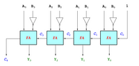
2. The following figure shows the four-bit Subtractor. Your inputs for this combinational circuit are A = 2 and B = 7. What is the outputs S3, S2, S1, and S0? You have to show how to get the outputs by indicating each carry bit.
(Note: You should show all the steps)
Transcribed Image Text:A3
B3
A2 B2
A, B1
A, B.
1
C3
C2
C
Co
FA
FA
FA
FA
C4
Y3
Y2
Y1
Yo
Expert Solution
Check MarkThis question has been solved!
Explore an expertly crafted, step-by-step solution for a thorough understanding of key concepts.
bartleby
This is a popular solution
bartleby
Trending nowThis is a popular solution!
bartleby
Step by stepSolved in 4 steps with 4 images
Knowledge Booster
Background pattern image
Learn more about
Need a deep-dive on the concept behind this application? Look no further. Learn more about this topic, electrical-engineering and related others by exploring similar questions and additional content below.Similar questions
- The encoder is the inverse operation of a decoder. It generates the binary code corresponding to the input value. The following figure shows a block diagram of 8-to-3 encoder. There are eight inputs, i.e. D7 through D0, and three outputs (binary code), i.e. B2, B1 and B0. Answer the following questions. (Note: You should show all the steps) 1. If the input D7 is high (or "1") and the other inputs are low (or "0"), what binary code does the encoder generate? 2. Draw the complete truth table of 8-to-3 encoder.arrow_forward4. Design a 2-Digit Magnitude Comparator using 1-Digit Magnitude Comparators and Appropriate Gates. Explain your design and/or the connections of your circuit.arrow_forwardQ1: The input waveforms in Figure below are applied to a 2-bit adder. Determine the waveforms for the sum and the output to the relation inputs by in carry constructing a timing diagram. A2 B1 B2 Cinarrow_forward
- (b) Using a synchronous binary counter as shown in Figure Q2(b), design and draw a counter to generate the following repeating sequences 2 to 14 repeatedly for a free running clock. If the circuit happens to enter any of the states 15 or 0 or 1, what are the next states of your circuit? A A Syn. Binary Counter Q3 Q2 Q1 Qo →Asyn. clear Syn. load CLK D3 D2 D1 Do ↑↑↑↑arrow_forwardSingle-choice (a), (b), (c), or (d). 1. A half-adder is characterized by (a) two inputs and two outputs (c) two inputs and three outputs 2. A full-adder is characterized by (a) two inputs and two outputs (c) two inputs and three outputs 3. The inputs to a full adder are A = (b) three inputs and two outputs (d) two inputs and one output (b) three inputs and two outputs (d) two inputs and one output 1, B = 0, C = 1. The outputs are = 1, Cout = 0 (a) = 0, Cout=1 (b) (c) = 0, Cout = 0 (d) Σ = 1, Cout = 1 4. A 3-bit parallel adder can add (a) three 2-bit binary numbers (e) three bits at a time (b) two 3-bit binary numbers (d) three bits in sequence 5. To expand a 2-bit parallel adder to a 4-bit parallel adder, you must (a) use two 2-bit adders with no interconnections (b) use two 2-bit adders and connect the sum outputs of one to the bit inputs of the other (e) use four 2-bit adders with no interconnections (d) use two 2-bit adders with the carry output of one connected to the carry input...arrow_forward5. The following figure shows the eight-bit Adder-Subtractor. Your inputs for this combinational circuit are A=16, B=31 and M = 1. What are the outputs S7, S6, S5, S4, S3, S2, S1, and S0? Express the outputs with a hexadecimal number. You have to show how to get the outputs by indicating each carry bit. (Note: You should show all the steps)arrow_forward
- I just need to know if my original work is correctarrow_forwardDigital Logic Design4-bit Binary Adder / Subtractorarrow_forwardDesign a counter which counts down, with the repeated sequence: (2, 1, 0, 2, 1, 0, ...) when the input to the counter circuit is 1. The counter doesn’t count (stays at the same state) when the input is 0. The circuit is to be designed by treating the unused states as don’t care conditions. Fill out state transition table, and draw state diagram and your schematic for the design. Use positive edge D flip flops in your design.arrow_forward
- The output expression for an AND-OR-Invert circuit having one AND gate with inputs A,B,C, and D and one AND gate with inputs E and F isarrow_forwardI want solution of just fourth one (d)arrow_forwardFor the circuit and inputs shown, draw the Q output. Assume Q is initially low. Clear is asynchronous. Be sure your diagram clearly indicates transitions of Q relative to all inputs. D Clock Cir Clock Cir Qi Q2arrow_forward
arrow_back_ios
arrow_forward_ios
Recommended textbooks for you
- Text book imageIntroductory Circuit Analysis (13th Edition)Electrical EngineeringISBN:9780133923605Author:Robert L. BoylestadPublisher:PEARSONText book imageDelmar's Standard Textbook Of ElectricityElectrical EngineeringISBN:9781337900348Author:Stephen L. HermanPublisher:Cengage LearningText book imageProgrammable Logic ControllersElectrical EngineeringISBN:9780073373843Author:Frank D. PetruzellaPublisher:McGraw-Hill Education
- Text book imageFundamentals of Electric CircuitsElectrical EngineeringISBN:9780078028229Author:Charles K Alexander, Matthew SadikuPublisher:McGraw-Hill EducationText book imageElectric Circuits. (11th Edition)Electrical EngineeringISBN:9780134746968Author:James W. Nilsson, Susan RiedelPublisher:PEARSONText book imageEngineering ElectromagneticsElectrical EngineeringISBN:9780078028151Author:Hayt, William H. (william Hart), Jr, BUCK, John A.Publisher:Mcgraw-hill Education,
Text book image
Introductory Circuit Analysis (13th Edition)
Electrical Engineering
ISBN:9780133923605
Author:Robert L. Boylestad
Publisher:PEARSON
Text book image
Delmar's Standard Textbook Of Electricity
Electrical Engineering
ISBN:9781337900348
Author:Stephen L. Herman
Publisher:Cengage Learning
Text book image
Programmable Logic Controllers
Electrical Engineering
ISBN:9780073373843
Author:Frank D. Petruzella
Publisher:McGraw-Hill Education
Text book image
Fundamentals of Electric Circuits
Electrical Engineering
ISBN:9780078028229
Author:Charles K Alexander, Matthew Sadiku
Publisher:McGraw-Hill Education
Text book image
Electric Circuits. (11th Edition)
Electrical Engineering
ISBN:9780134746968
Author:James W. Nilsson, Susan Riedel
Publisher:PEARSON
Text book image
Engineering Electromagnetics
Electrical Engineering
ISBN:9780078028151
Author:Hayt, William H. (william Hart), Jr, BUCK, John A.
Publisher:Mcgraw-hill Education,