Picture this: You are sitting high up in the stands at an overly crowded auto racing event. Below, sleek Formula One cars line the track. The starting pistol goes off with a bang and cars flash by. How are Formula One cars able to accelerate at lightning-fast speeds? One contributing factor is their lightweight, composite build. Now, composite materials are being used in everyday vehicles as well.
Composite materials are heterogenous and made up of two or more components of varying properties. These properties give composites unique characteristics, like super strength. Not only are composites strong but they’re also lightweight — making them the perfect option for vehicle wheel rims.
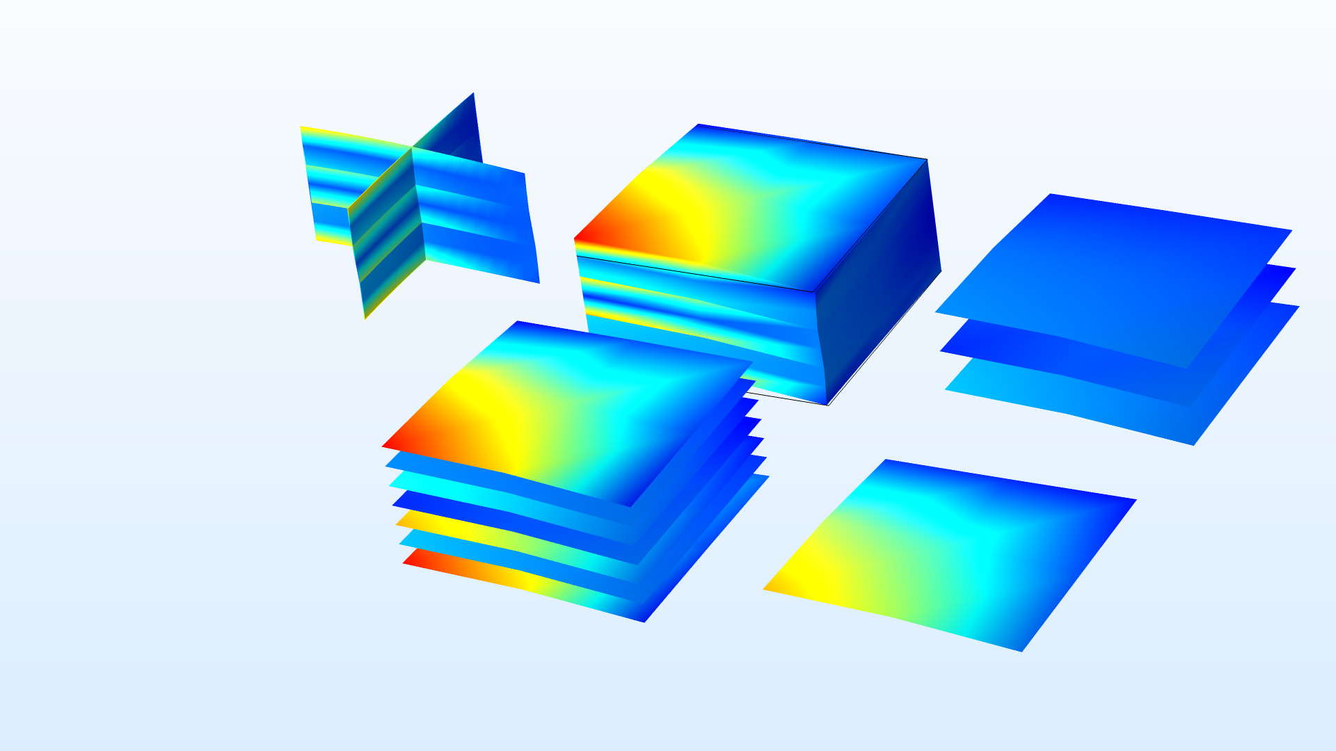
[画像:An image showing 5 different aspects of a 3-layer composite laminate.]
A thick, three-layer laminate, an example of a composite material.
Compared to steel and aluminum wheel rims, composite wheel rims have lower values of unsprung mass, which leads to wheels with better:
Composite wheel rims also transmit less high-frequency vibrations because they have better damping abilities than metal wheel rims.
Nothing is perfect, and composite materials are no exception. They are manmade, which makes them difficult to reuse and dispose of, and they’re expensive. In fact, some composite wheel rims can cost up to 12,000ドル for a set!
Since composite wheel rims are still a relatively new concept, developers and manufacturers in the automotive industry could be wary of fully trusting them as an alternative to aluminum and steel rims. Simulation can help alleviate these worries by showing how composite wheel rims will function in the real world and improving composite wheel rim designs from the start.
In this example, a composite wheel rim with a carbon-epoxy laminate is modeled using the Composite Materials Module, an add-on to the Structural Mechanics Module and COMSOL Multiphysics®.
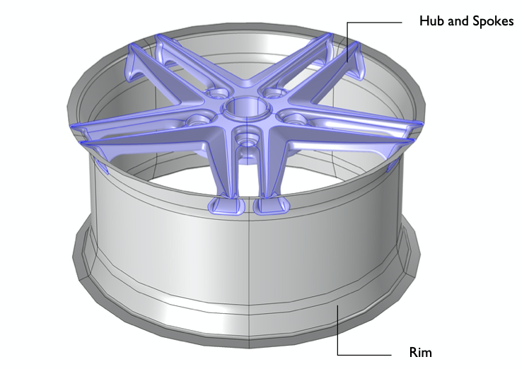
The geometry of the composite wheel rim consists of two main parts:
[画像:An image of the geometry for the composite wheel rim model.]
Geometry of the composite wheel rim model.
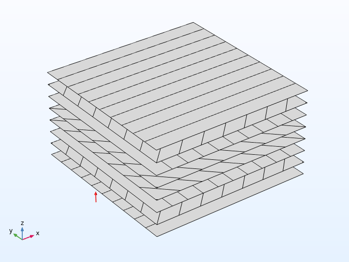
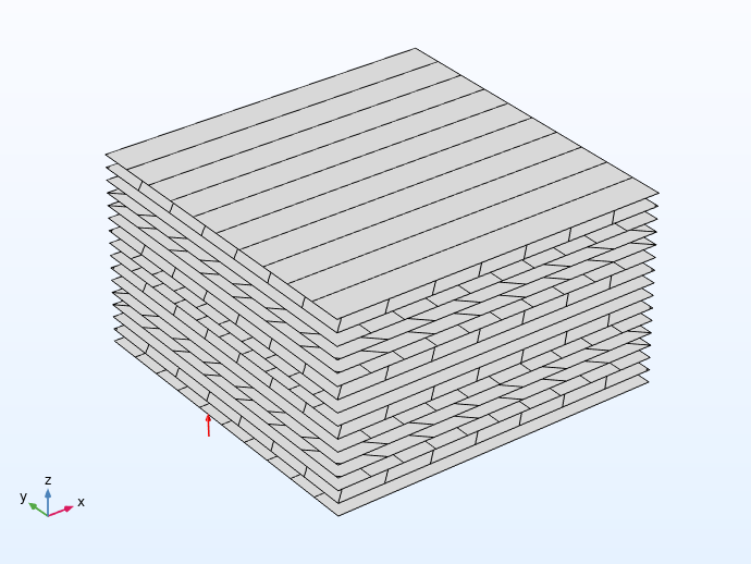
The surfaces of the rim region are made up of 16 laminate layers, and the hub-spoke region is made up of 8. Both regions consist of a balanced ply layup. The stacking sequence for the hub and spoke region (using customary notation for laminate layups) is [0/45/90/-45]s, and for the rim region it is [[0/45/90/-45]s]2.
Each ply is made from a carbon-epoxy material, or carbon fiber, and has a thickness of 0.4 mm. (Carbon-epoxy can be 10 times stronger than steel!)
Examples of the stacking sequence in the hub-spoke region (left) and the rim region (right).
Two types of analyses are conducted:
Two contributions to the static load are considered:
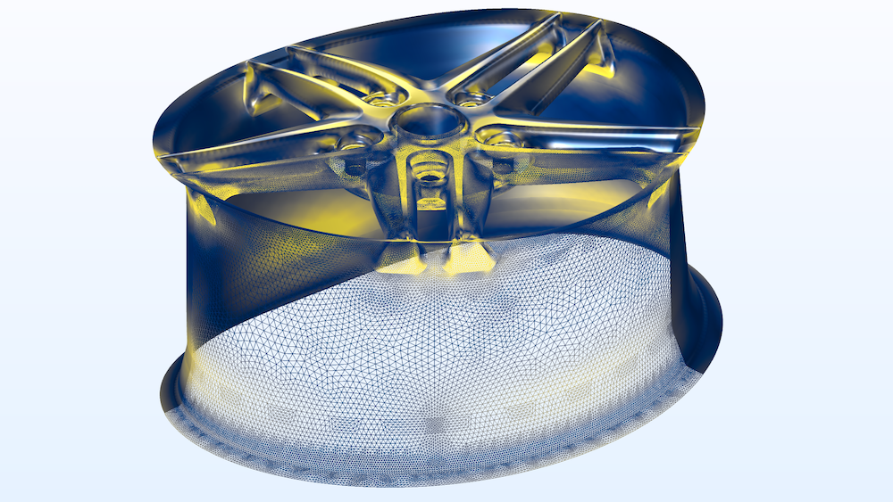
The von Mises equivalent stress can be used to get an overview of the stress distribution, even though it is not directly applicable to evaluating the failure risk in a composite. High von Mises stresses appear in the spoke region where the tire load is acting.
[画像:A plot of the von Mises stress distribution for a composite wheel rim design.]
Example of von Mises stress distribution in a composite wheel rim.
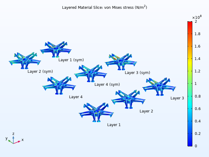
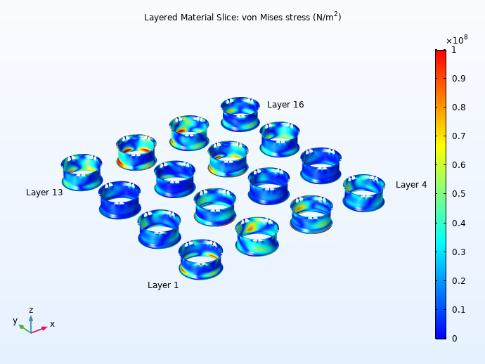
Below, you can see that stresses are high in Layer 3 of the hub-spoke region (left) and layers 14 and 15 of the rim region (right).
Examples of von Mises stress distribution in each layer of the hub-spoke region (left) and rim region (right).
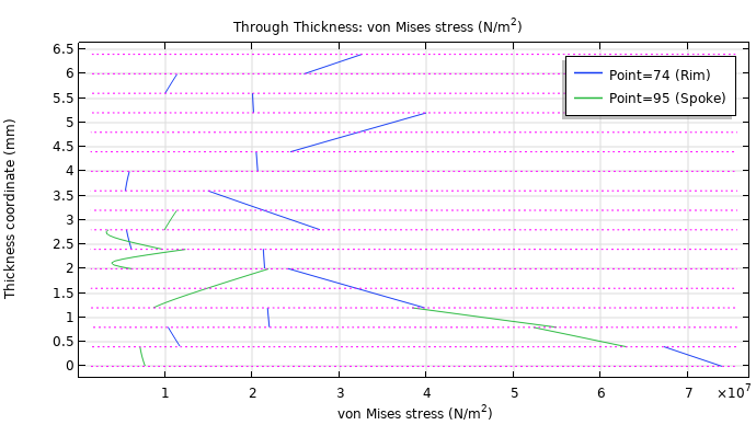
You can also analyze the through-thickness variation of the stress at a particular point on the rim and spoke region. Here, you can see different stress levels in each ply. At this point, the maximum stresses are found in the two outermost layers of the rim and spoke regions, which is common.
[画像:A through-thickness plot of the von Mises stresses in a wheel rim.]
Through-thickness variation of von Mises stress for particular points on the rim and spoke regions.
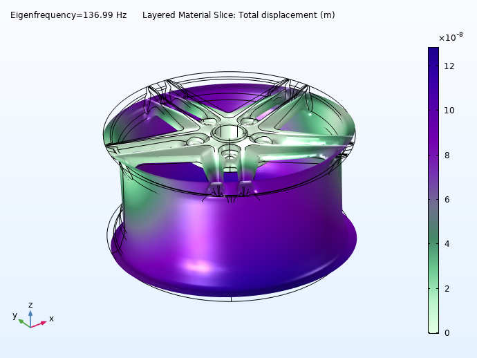
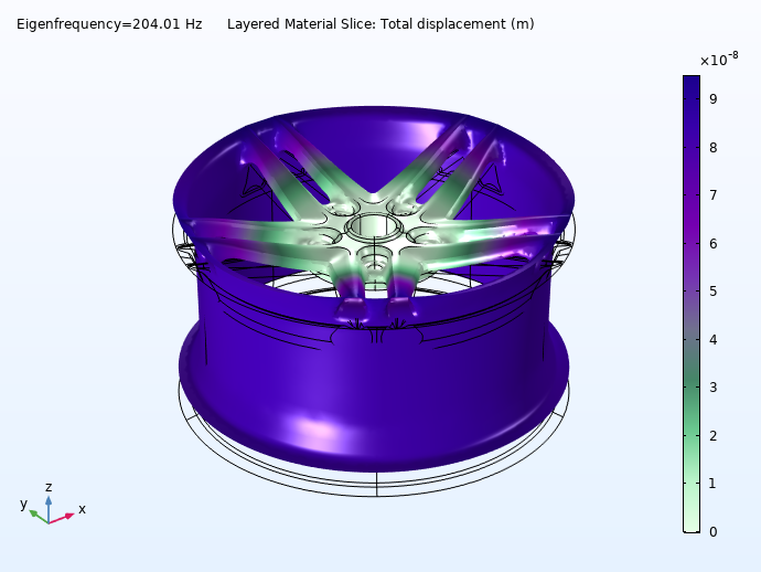
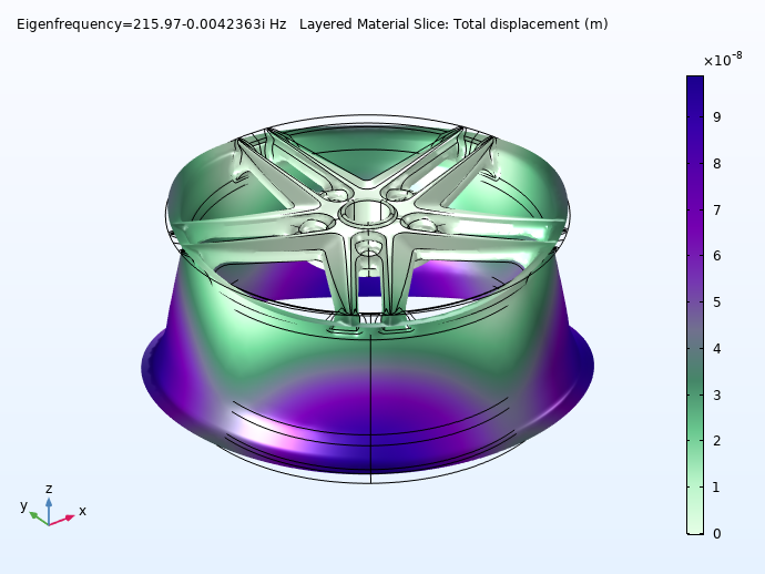
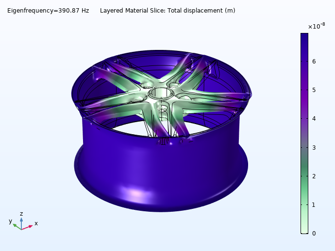
Moving forward to the prestressed eigenfrequency analysis, you can view how the wheel rim’s rotational speed affects its various mode shapes. Here, you can see the wheel’s first four eigenmodes when it’s rotating at 3000 rpm. (For a quick estimate, the velocity in km/h is the rpm value divided by 10, so this is of the order of 300 km/h or 200 mph.)
The first eigenfrequency found for the composite wheel rim (135 Hz) corresponds to approximately 8000 rpm, which is well above the normal operating range of a wheel. Since the carbon-epoxy composite material has a high strength-to-weight ratio, the rim can obtain a high value of the eigenfrequency.
As composite materials become more popular in the automotive industry, the importance of well-designed composite wheel rims is rising. In this example, you are able to view how you can efficiently model and analyze composite wheel rims by performing stress and modal analyses in the Composite Material Module.
Download the Stress and Modal Analysis of a Composite Wheel Rim tutorial model by clicking the button below. Doing so will take you to the Application Gallery example.
By providing your email address, you consent to receive emails from COMSOL AB and its affiliates about the COMSOL Blog, and agree that COMSOL may process your information according to its Privacy Policy. This consent may be withdrawn.
Despite the reservation that Von Mises “is not directly applicable to evaluating the failure risk in a composite” is seems a bit miss leading to use it anyway. Von Mises is a yield criterion for ductile materials. It is not for failure detection in brittle materials. This is important and therefore worth to repeat 🙂