I have an IR pyroelectic flame sensor which detects flames within the 8-10hz of flame flicker. I am new to the ADC world so any help is very appreciated.
Documentation: https://pyreos.com/wp-content/uploads/2020/11/Pyreos-Analog-TO-Flame-Sensor-One-Channel.pdf
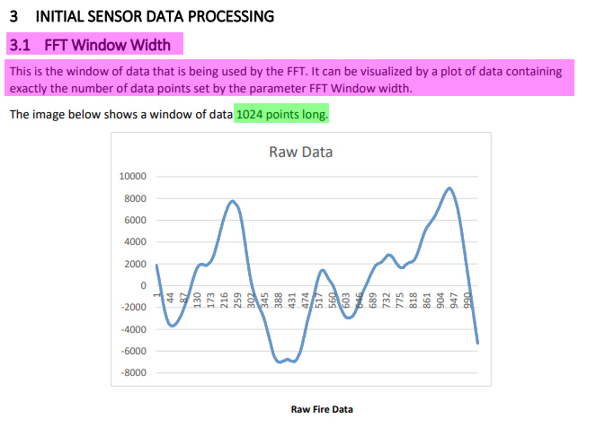
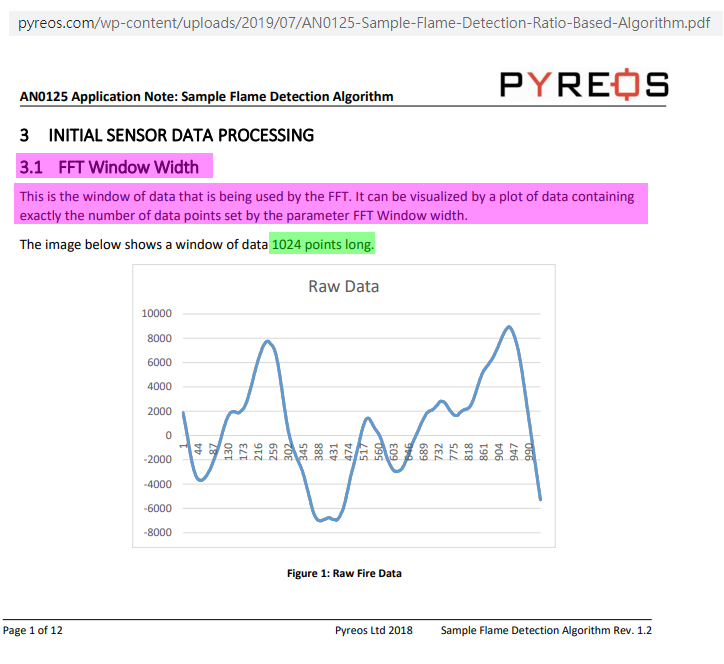
I have the py0573 which has a bandpass filter for CO2 spectrum. According to the company's algorithm recommendation, I basically need to plot/detect FFT (Fast Fourier transform) bins from the 5-15hz frequency to determine a "flame" exists on the FOV of the sensor.
In order for me to read the signal from the half-rail, I installed a MCP3008 to my RPi model 4 and set the signal to CH0 of the ADC. I also included a .1uf decoupling capacitor.
Using the below code, I am able to get some readings from the sensor, but I am unsure if this sampling rate is setup correctly or not.
Questions:
- How do I setup the read from the ADC within the 8-10hz range?
- Is there a way to plot this with FFT? Do I need FFT or can I determine the total sum values from ADC to indicate a "flame"?
- Is the frequency setup basically the loop speed of Python or the spi.max_speed_hz option?
- Am I converting the raw ADC values correctly using numpy interp?
- If the sensor has a max 10hz frequency then I need to double that for my sample rate?
- Should I be using Adafruit's adafruit-circuitpython-mcp3xxx package instead?
With the below code, I am able to see the values change when I light a flicker match but its a bit inconsistent and only changes when the flame is flickering and not when its still.
import spidev
from numpy import interp
import time
import datetime
from datetime import timedelta
# Start SPI connection
spi = spidev.SpiDev() # Created an object
spi.open(0,0)
# Read MCP3008 data
def analogInput(channel, hz):
 spi.max_speed_hz = hz
 adc = spi.xfer2([1,(8+channel)<<4,0])
 data = ((adc[1]&3) << 8) + adc[2]
 return data
data_list=list()
init_time = datetime.datetime.now()
while True:


 output1 = analogInput(0, 1000000)
 output1 = interp(output1, [0, 1023], [0, 100])

 data_list.append(output1)
 if init_time < datetime.datetime.now() - timedelta(seconds=2):

 print("min" + str(min(data_list)))
 print("max" + str(max(data_list)))
 print("avg" + str(sum(data_list)/len(data_list)))
 data_list=list()
 init_time = datetime.datetime.now()


 time.sleep(.001)
-
1Comments are not for extended discussion; this conversation has been moved to chat.goldilocks– goldilocks2021年03月10日 18:51:23 +00:00Commented Mar 10, 2021 at 18:51
1 Answer 1
Question
How to use Rpi python MCP3008 ADC to help analyse flame flicker signals?
Notes
A py0573 bandpass filter is used for CO2 spectrum
To determine if a "flame" exists on the FOV of the sensor, the vendor recommends a plot/detect FFT bins from the 5-15hz frequency.
Electrical Characteristics
Max. Voltage (+V) = 8.0 V
Min. Voltage (+V) = 2.7 V
Output voltage normalised around mid-rail
Time Constant = ~12 ms
Op-Amp with 10 GΩ feedback resistor
Answer
Part 1 - Using MCP3008 to read raw data
First thing first is to prepare 1,024 flame sensor readings for FFT. (See Reference 6 and Appendix B below for more details.)
/ to continue , ...
References
(1) Thin Film Pyroelectric Flame Sensor - PY-ITV-FLAME–TO39(2+1) R5.2 - Pyreos
(2) MCP3008 SPI 2.7V 8-Channel 10-Bit A/D Converters - MicroChip
(3) Rpi Reading MCP3008 10 bit ADC Result Problem - Rpi SE 2019may22
(4) Flame Detector - Wikipedia
(5) Tips To Select The Right Flame Detector - Edward Naranjo, Emerson Automation Solutions 2019mar06
(6) AN0125 Application Note: Sample Flame Detection Ratio Based Algorithm - Pyreos
(8) MCP3008 10 Bit ADC Raspberry Pi Python Library 0.1a3 (pip install mcp3008) - PiPy.org
(11) 32/64/128/256/512/1024/2048/4096 Point FFT Core - IPCores
Appendices
Appendix A - Pyroelectric Flame Sensor PY-ITV Datasheet Summary
Introduction
The Pyreos thin film pyroelectric infrared flame detectors offer exceptionally high responsivity, a wide field of view of typically 100° (*subject to filter band pass specification) and class leading rapid recovery from thermal and electrical shocks (<1 second downtime). This current mode sensor has excellent signal to noise at the signature 8-10 Hz flicker range of a flame, and can provide accurate discrimination of flame sources in triple IR flame detection systems.
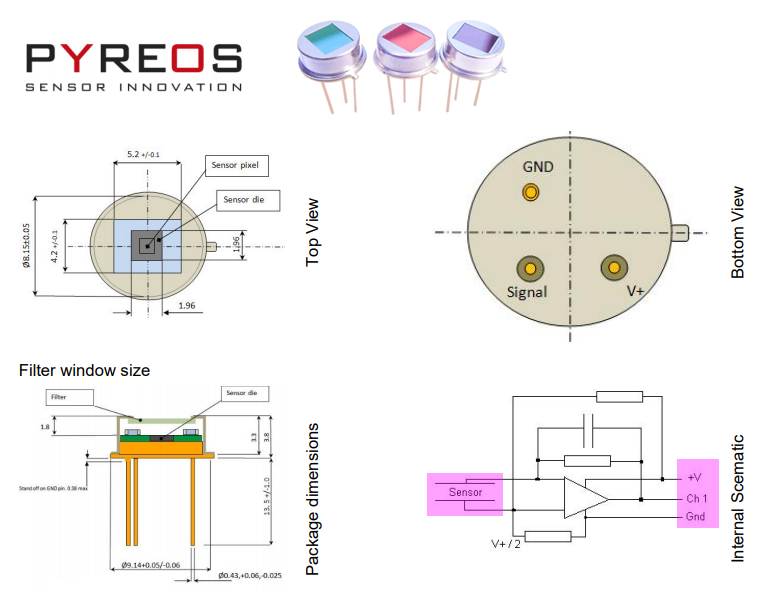
The sensor element is built into a low noise circuit that has an internal CMOS op amp with a 10GΩ feedback resistor outputting a voltage signal centred around half the supply rail.
Sensor Characteristics
Filter aperture = 5.2 mm x 4.2 mm
Element size = 1000 μm x 1000 μm
Package = TO39
Responsivity = 1 150,000 V/W
D* = 3.5 x 108 cm√Hz/ W
Noise = Mean 70 μV√Hz
Field of View = Typical 100°
Electrical Characteristics
Max. Voltage (+V) = 8.0 V
Min. Voltage (+V) = 2.7 V
Output voltage normalised around mid-rail
Time Constant = ~12 ms
Operating Temperature = -40 to +85 °C
Storage Temperature = -40 to +110 °C
Op-Amp with 10 GΩ feedback resistor
Filter As per Filters Available table
Appendix B - Package Info and Internal Schematic
Appendix C - Example Raw Data for FFT
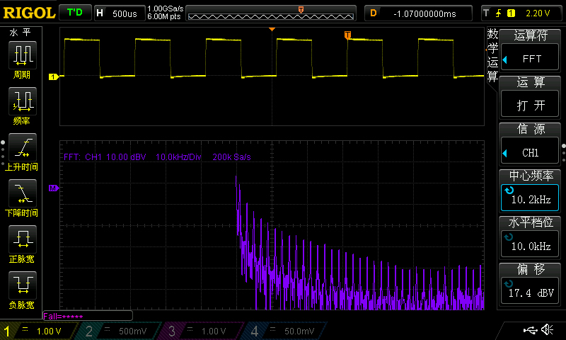
Appendix D - Rigol DS1504Z 50MHz 1Gsp/s Scope 1KHz square wave signal FFT Test
/ to continue, ...
Explore related questions
See similar questions with these tags.