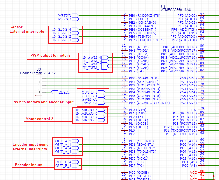
I'm working on a microcontroller board that also features a couple of motor drivers which can be controlled using PWM signals. I also intend to precisely control the positioning of the motors using their encoder outputs, and I've wired the lines so that the A signal outputs from the encoders are connected to the MCU's external interrupt pins and the B signal outputs are connected to normal digital inputs. For the rest of the external interrupt pins I want to wire those to inductive sensors used for homing the motors. Lastly, I've connected the PWM pins for the drivers to PWM pins on the MCU and the pins for direction control to digital output pins on the MCU. I'll also mention that two encoder B outputs are connected to timer pins T1 and T0.
I have 3 questions:
- For PWM control of pins PH3(OC4A)/PH4(OC4B)/PH5(OC4C)/PH6(OC2B)/PB6(OC1B)/PB7(OC0A), what timers do I need to use? Timers 0, 1, 2 and 4, with their associated pins?
- If I have to use timers 0 and 1, will the functionality of pins PD6(T1) and PD7(T0) be impacted or will I still be able to read the encoder signals from these?
- Is my strategy for using the encoders feasible? When the A signals activate the external interrupts I'll verify if the B pins are also active and based on this I will increment or decrement the steps for each motor.
-
\$\begingroup\$ The AVR-C does not seem to be relevant. \$\endgroup\$Justme– Justme2024年07月10日 21:49:25 +00:00Commented Jul 10, 2024 at 21:49
1 Answer 1
For PWM control of pins PH3(OC4A) / PH4 (OC4B) / PH5 (OC4C) / PH6 (OC2B) /PB6 (OC1B) / PB7 (OC0A), what timers do I need to use? Timers 0, 1, 2 and 4, with their associated pins?
As the digit in the names suggest PH3 (OC4A) / PH4 (OC4B) / PH5 (OC4C) this belongs to Timer 4. And PH6 (OC2B) / PB6 (OC1B) — Timer 2 and Timer 1 and finally PB7 (OC0A) is a Timer 0.
If I have to use timers 0 and 1, will the functionality of pins PD6 (T1) and PD7 (T0) be impacted or will I still be able to read the encoder signals from these?
Yes, sure you can use it. T1 and T0 can be used as an external clock input for Timer 1 and Timer 0. But by default, Timers are clocked from an internal clock source.
Is my strategy for using the encoders feasible? When the A signals activate the external interrupts I'll verify if the B pins are also active and based on this I will increment or decrement the steps for each motor.
Hard to say, looks legit so far.
-
\$\begingroup\$ Is it at all possible to configure the MCU so that PB7 and PB6 use other timers for PWM? \$\endgroup\$hdaniu– hdaniu2024年07月11日 10:33:57 +00:00Commented Jul 11, 2024 at 10:33
Explore related questions
See similar questions with these tags.