I'm currently diving into the task of cracking the data stream protocol for a generator control system. There's this setup with a control box sitting next to the generator, and a remote switch in the mix. The control box can do its own thing, firing up and shutting down the generator, but you can also override it with the remote.
The remote switch, it's got five LEDs showing the fuel levels, plus a couple of extras: one for automatic mode and another for manual override. And a momentary button for switching between modes. Surprisingly, there are just four wires hooked up to the switch. Using a multimeter, I've figured out that:
- Pin1 is +5V
- Pin2 is GND
- Pin3 is hooked up to the button through a 1K pullup resistor
- Pin4 seems to be the UART TX line
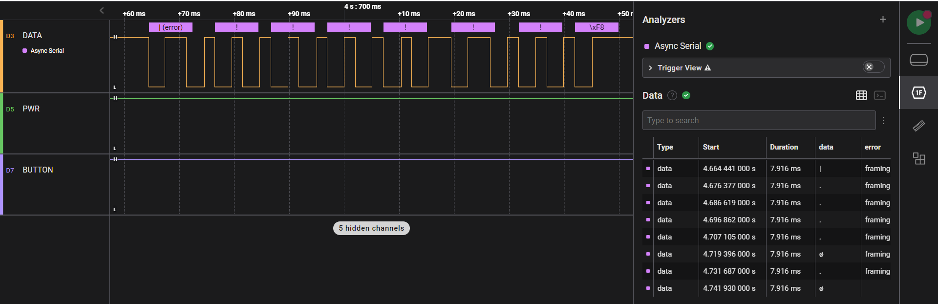
I've done some sniffing with a logic analyzer and clocked the transmission speed at 1200 bps. But, truth be told, I'm stumped on what the actual data is saying. I've added a screenshot of what the logic analyzer was able to decode.
Any of you fine folks have some tips or ideas on how I could go about deciphering the info coming through the UART interface? I'd be super grateful for any help!
-
4\$\begingroup\$ Looks less like UART and more like some sort of PWM code to me. Like something that might come out of an IR remote. \$\endgroup\$Dave Tweed– Dave Tweed2023年09月21日 21:01:53 +00:00Commented Sep 21, 2023 at 21:01
-
\$\begingroup\$ The low periods seems to be constant, so the high periods probably contain 1 or 0. \$\endgroup\$Jens– Jens2023年09月22日 14:37:32 +00:00Commented Sep 22, 2023 at 14:37
2 Answers 2
it looks like some sort of pulse width signalling all the lows are the same width but the highs are two different widths.
This can be decoded by UART by making the symbol duration greater than a wide pulse and no more than than a narrow pulse and a rest.
It looks like a rest (low) is 1.5ms. a 1 is 2ms and a 0 is 1ms
with 8N1 the most you can have is 9 spaces in a row so the long pulse constrains the baud date to no more than 9/2ms or 4500 baud
and with a 0 and a rest being 2.5ms combined that can take up to 10 cycles so 10/2.5ms that comes out to 4000 baud,
so set your UART to approx 4250 baud 8N1 and and feed it an inverted copy of the signal and is shoul see a should get a signal looking like a break (aka long space) followed by 14 bytes of data, each byte being a bit-mapped representation of the pulse width
If you need to generate this signal a UART is not the right solution because it won't easily give the even width rests between the data bits.
As Dave Tweed suggests it is likely an IR remote control protocol.
NEC uses a pulse distance encoding scheme. RC5 uses Manchester encoding.
There are other protocols so searching for "IR remote protocol" will yield a lot of information.
-
\$\begingroup\$ Pin3 is only connected to the button via a pull-up resistor. But I'm pretty sure you're on to something with the PWM/IR encoding. \$\endgroup\$JCorradoIII– JCorradoIII2023年09月21日 21:53:01 +00:00Commented Sep 21, 2023 at 21:53
-
\$\begingroup\$ I adjusted the answer @JC03. \$\endgroup\$user319836– user3198362023年09月22日 01:49:20 +00:00Commented Sep 22, 2023 at 1:49
Explore related questions
See similar questions with these tags.