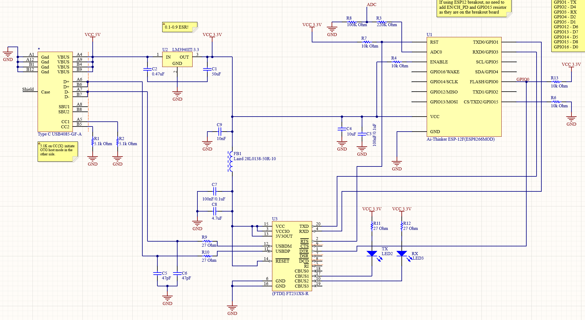
I've challenged myself to make a custom ESP8266 (ESP12S) board. I'm having a problem I cannot decipher: The PC sees the USB device, and I can successfully upload my code through the Arduino IDE, but after the upload it does nothing. Uploaded blink and nothing happens.
I'm using a LM3940 to get my 3V3 and a FT231X for the UART.
I've put this schematic together on a breadboard, breakouts for the ESP & UART. I checked the voltage across the ESP's Vcc & Gnd: while uploading it is 3V3, afterward it drops to ~2V.
Is there an obvious fault here? Or is breadbording this just not good enough?
My suspicion is that this is a power delivery issue, so I swapped to a TPS63051 but the PC did not even recognize the device with that in place. Got 1V between the ESP Vcc & Gnd. I imagine that part really does not like to be on a breadboard, without any load it was producing 3V3 no problem.
-
1\$\begingroup\$ Usually the program and reset (driven by DTR, RTS) have a circuit that leaves them floating when both are high or low. Have you tried controlling the pins with a terminal program (or Python or whatever) what happens if you release the reset while the programming pin is in a state that allows the code to run? \$\endgroup\$Justme– Justme2023年07月20日 17:17:45 +00:00Commented Jul 20, 2023 at 17:17
-
\$\begingroup\$ @Justme Can you share an example of such a terminal program? The UART/MCU connection was taken from a FTDI232 serial module. \$\endgroup\$MustSeeMelons– MustSeeMelons2023年07月20日 20:24:02 +00:00Commented Jul 20, 2023 at 20:24
-
\$\begingroup\$ For which OS? And the circuit for programming mode entry would not be in a FTDI example but in ESP8266 example and there's plenty of them. \$\endgroup\$Justme– Justme2023年07月20日 20:34:21 +00:00Commented Jul 20, 2023 at 20:34
-
\$\begingroup\$ so why did you directly connect DTR to io 0? that will not work to enter/leave flashing mode \$\endgroup\$Juraj– Juraj2023年07月21日 04:52:00 +00:00Commented Jul 21, 2023 at 4:52
-
\$\begingroup\$ @Justme Windows, please. Juraj I was following how an FTDI USB module was wired. Upload works fine. How should it be wired? \$\endgroup\$MustSeeMelons– MustSeeMelons2023年07月21日 07:19:21 +00:00Commented Jul 21, 2023 at 7:19
1 Answer 1
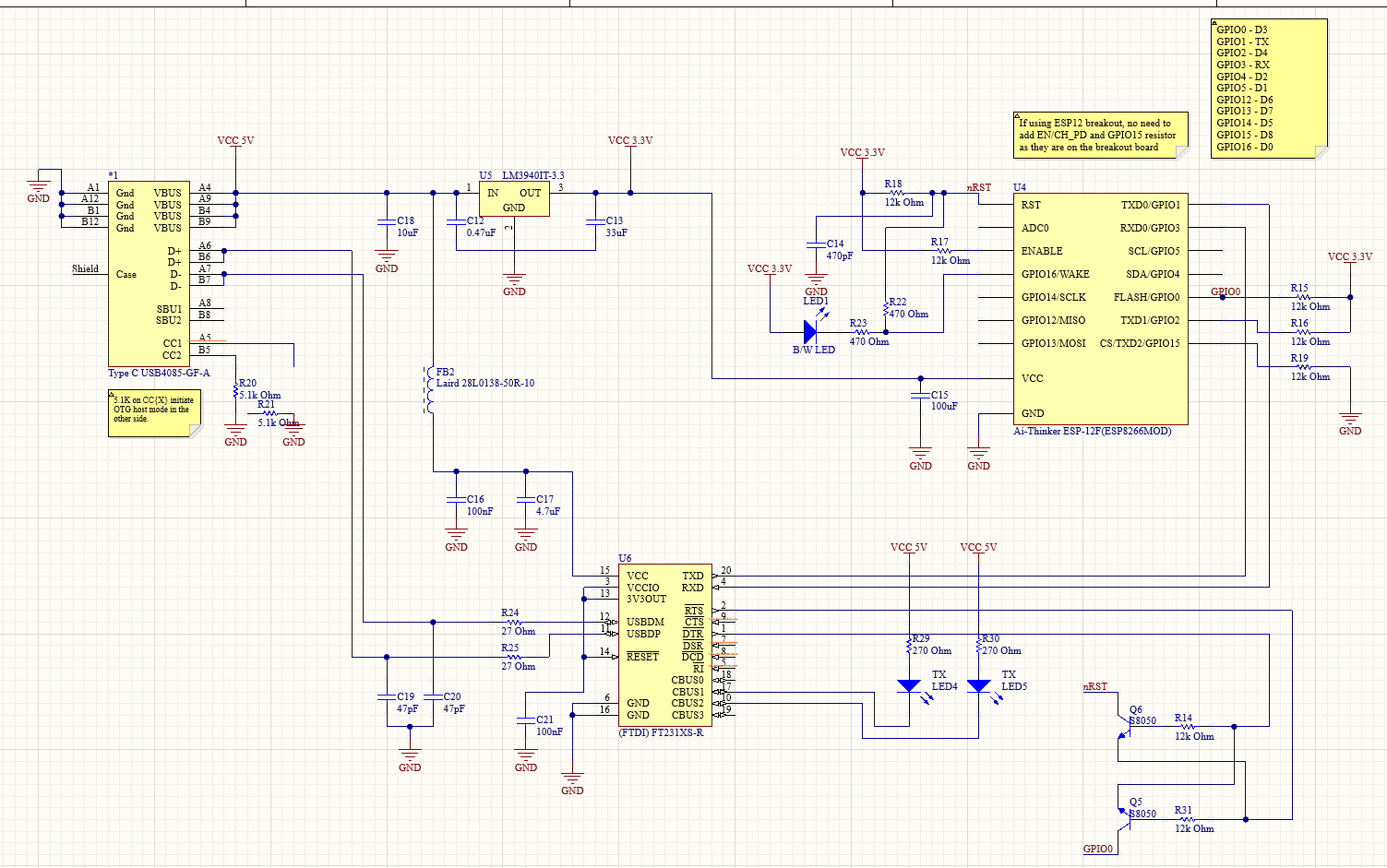
After a month of standstill, I finally figured it out. Firstly I changed the UART upload circuit to the one in the reference design. It uses a pair of transistors. I got precisely the same result - it uploads but does not boot.
Put it on a separate breadboard to check the minimum necessary for it to boot. Oddly enough it needed only Vcc and GND. Worked as expected.
Afterward, I ripped out all the connections between the MCU and UART to replicate the scenario from the other breadboard. It did not work. And then it hit me - I used a longer wire and the decoupling cap was further away.
Once I used a shorter wire & a cap right next to the MCU it all started working on the main breadboard.