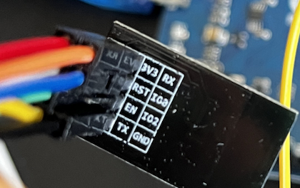
I've been trying to connect the ESP8266 Wifi module to my Arduino Leonardo and program the wifi module from it (using Arduino IDE). However, I'm not able to get the connection established! I tried many tutorials but I simply may be missing out on something. In the schematics, I tried to respect the colors of the wires exiting out on the module.
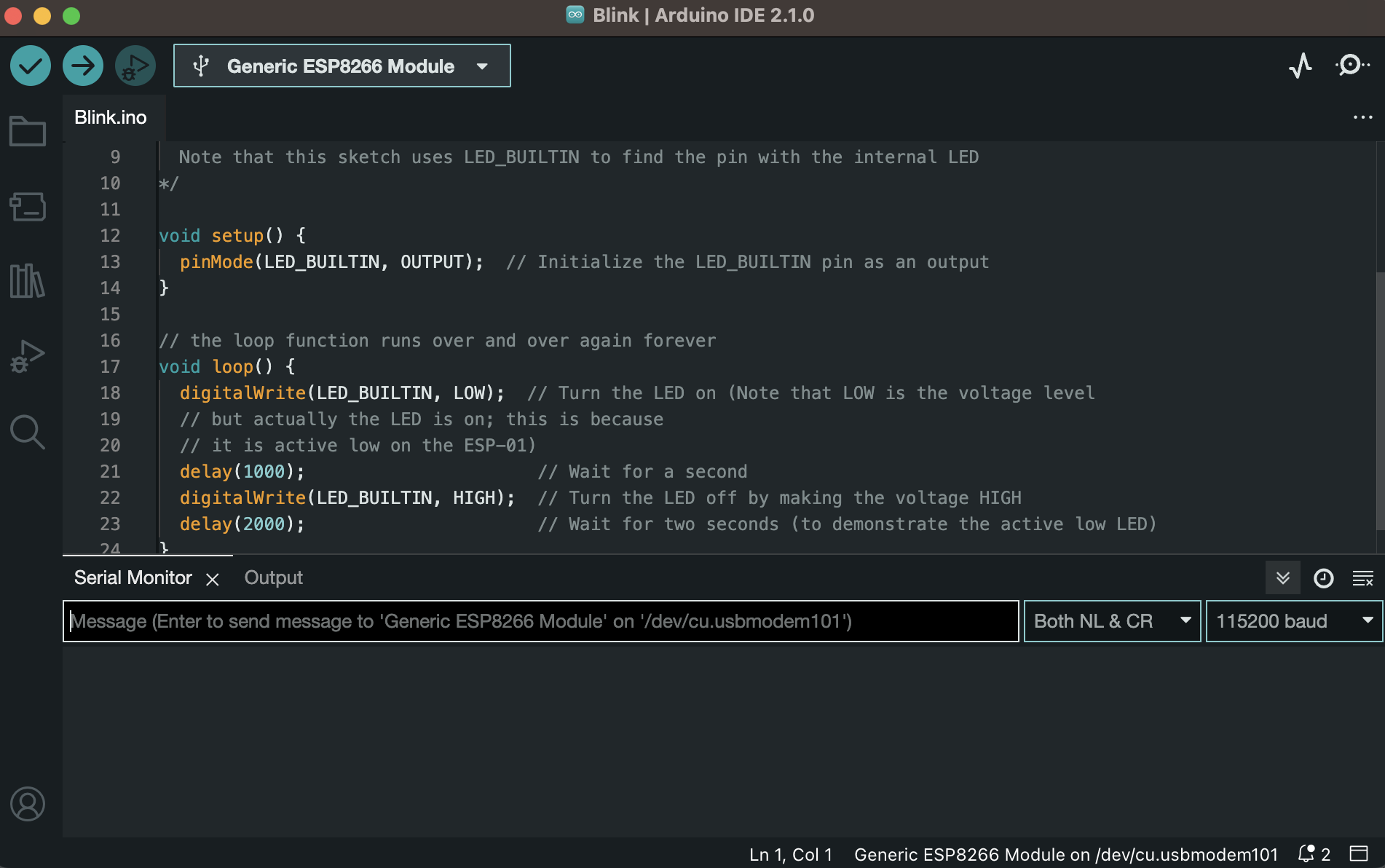
In Arduino IDE I've installed "Generics ESP8266 Module" and set the port to the port connected to Arduino Leonardo. It says "[not connected]" after reseting the Leonardo, but then I select the Arduino Leonardo port again in Tools and it disappears. However, I get no response from writing the command "AT+RST" into the serial monitor, or any other AT command for that matter.
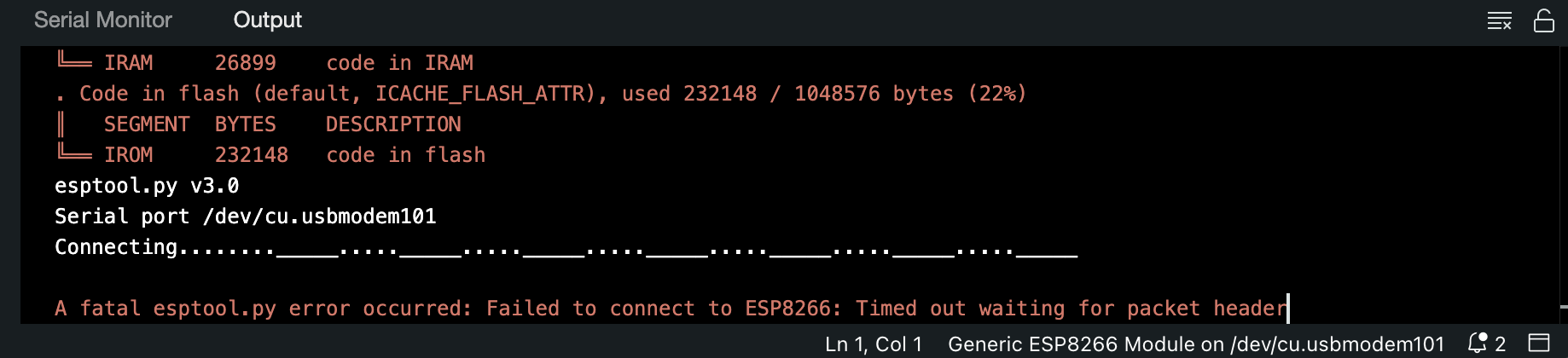
When I try to upload the Blink code, they are not connected (last image).
schematic
simulate this circuit – Schematic created using CircuitLab
enter image description here enter image description here enter image description here enter image description here
-
\$\begingroup\$ Your RX/Tx connections are wrong. The Tx of the Arduino needs to connect to the Rx of the ESP, and the Rx of the Arduino connects to the Tx of the ESP. \$\endgroup\$LordTeddy– LordTeddy2023年04月25日 11:19:46 +00:00Commented Apr 25, 2023 at 11:19
-
\$\begingroup\$ @LordTeddy I thought of that, but the tutorials I've seen always say to connect Rx-Rx and Tx-Tx. For example: donskytech.com/program-esp8266-esp-01-with-arduino or electronicshub.org/esp8266-arduino-interface \$\endgroup\$ludicrous– ludicrous2023年04月25日 11:21:23 +00:00Commented Apr 25, 2023 at 11:21
-
\$\begingroup\$ @ludicrous Did you try swapping them? \$\endgroup\$Edin Fifić– Edin Fifić2023年04月25日 11:28:47 +00:00Commented Apr 25, 2023 at 11:28
-
\$\begingroup\$ @EdinFifić I did, but still didn't work (writing "AT" into serial monitor didn't produce "OK" and uploading of code failed) \$\endgroup\$ludicrous– ludicrous2023年04月25日 11:29:54 +00:00Commented Apr 25, 2023 at 11:29
-
\$\begingroup\$ Ahh, that's my mistake, that is the right way round for what you're doing \$\endgroup\$LordTeddy– LordTeddy2023年04月25日 11:30:24 +00:00Commented Apr 25, 2023 at 11:30
1 Answer 1
You use the approach for an Uno where the RX/TX pin of the board are RX and TX pins of the USB chip so you can use the USB chip of the Uno as an USB to TTL Serial adapter.
On Leonardo there is no USB chip. The Atmega32u4 has native USB. The RX and TX of Leonardo are Serial1 so you have to bridge Serial (USB) to Serial1 with the SerialPassthrough basic example uploaded into Leonardo.
Wire RX to TX between Leonardo and the esp8266. Set the baud-rate in the SerialPassthrough sketch to 115200 baud.
The 3.3 V pin of Leonardo may not be able to provide enough current to run WiFi on the esp8266.
Explore related questions
See similar questions with these tags.