I have a 5 V relay module connected to WeMos D1 board. The load is a small electric cooker.
The code turns on and off the relay every 5s for testing purposes.
digitalWrite(pin,HIGH); delay(5000);
digitalWrite(pin,LOW); delay(5000);
However, the green light and red light are always on. there is no switching happening. An onboard led on the WeMos D1 board is blinking every 5s.
int pin = 14;
void setup()
{
 pinMode(pin, OUTPUT);

}
void loop()
{
 digitalWrite(pin,HIGH);
 delay(5000);
 digitalWrite(pin,LOW);
 delay(5000);
}
Thank you!
3 Answers 3
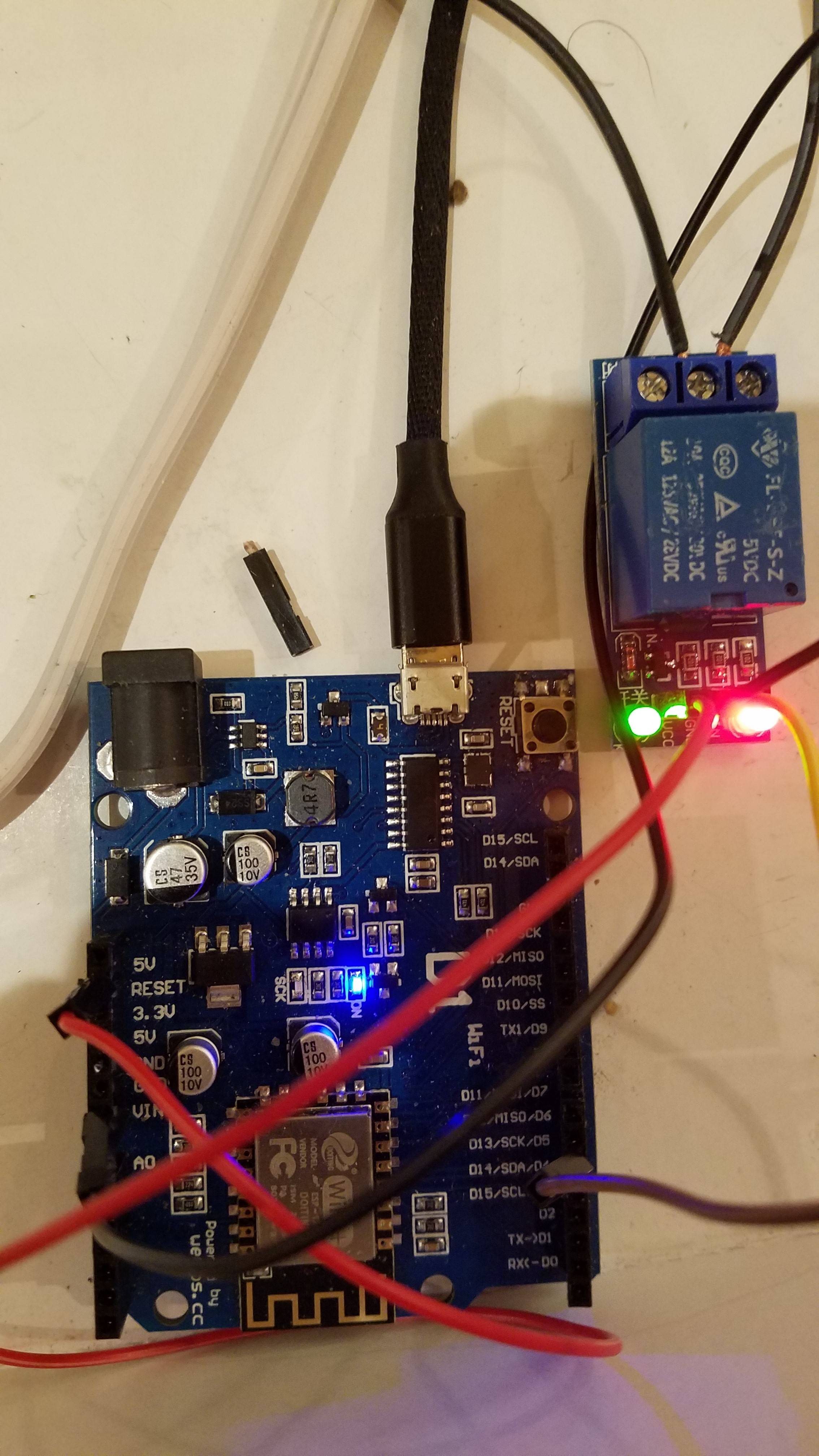
It's very difficult to tell from the poor quality images posted but it appears that you may have connected the wires on the left side of the board one pin out of position.
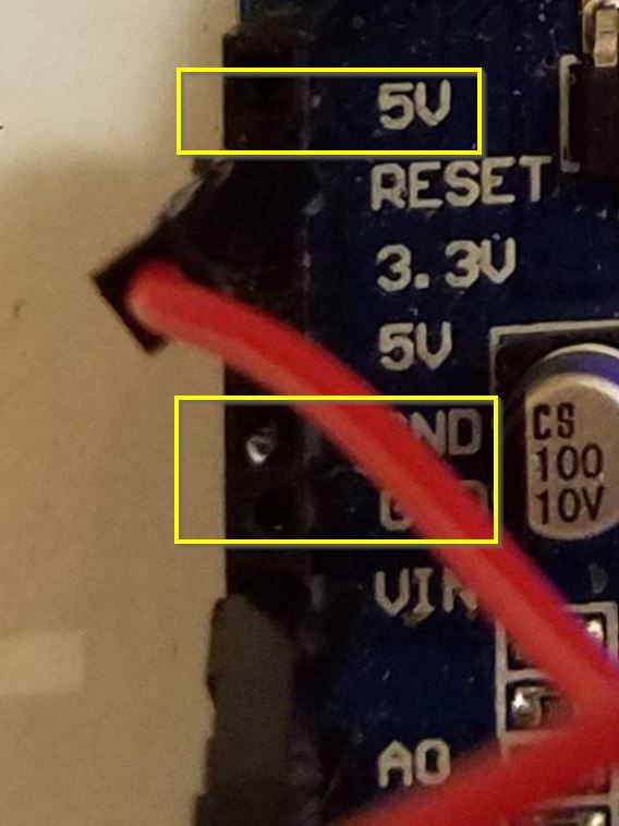
Figure 1. The relay module requires 5 V so it should be powered from the 5V pin on the WEMOS board. The relay module GND should be connected to any GND pin on the WEMOS.
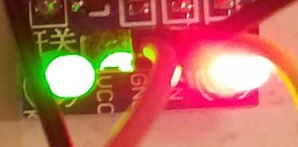
Figure 2. Connections on the relay board are unclear. Here it appears that you have connected in sequence red, yellow, black. This doesn't match the colours on the WEMOS.
Note the order on the relay module is VCC, GND and IN.
schematic
simulate this circuit – Schematic created using CircuitLab
Figure 3. Wiring diagram.
You expressed fear of circuit diagrams in your original post. There is no need to fear them. They are the simplest unambiguous way to show the scheme of the circuit. You can see that in this case it's ridiculously simple to understand.
There should be no connection between the WEMOS and the mains wiring other than the through the isolation of the relay.
-
\$\begingroup\$ Thank you @Transistor. Wiring was correct. Turning off requires conditionally activating a 20K resistor (PULLUP). This is apparently done through code. I will add a solution below. \$\endgroup\$Tims– Tims2021年03月28日 15:02:53 +00:00Commented Mar 28, 2021 at 15:02
-
\$\begingroup\$ Typically the microcontroller's outputs are push-pull. You only need a pull-up if the output is open drain only. Do you know what yours is? \$\endgroup\$Transistor– Transistor2021年03月28日 15:06:26 +00:00Commented Mar 28, 2021 at 15:06
-
\$\begingroup\$ Not sure, but relay is acting perfectly after using INPUT_PULLOUT instead of HIGH pinmode for deactivating the relay. \$\endgroup\$Tims– Tims2021年03月28日 15:10:40 +00:00Commented Mar 28, 2021 at 15:10
-
1\$\begingroup\$ OK. Accept your answer instead of mine if yours is correct. Otherwise you'll confuse anyone looking for the solution. Thanks. \$\endgroup\$Transistor– Transistor2021年03月28日 15:21:59 +00:00Commented Mar 28, 2021 at 15:21
- make sure your 3 wire interface uses a common ground with relay coil and logic supply
- Make sure you are using 5V and not 3.3V for the 5V coil - if it is good code then the voltages will switch on the interface which you can easily measure or use 1k R+LED as a crude logic probe.
Since the 3 wire interface is low current it is better to use twisted pairs of AWG24 CAT3 or similar for EMI reasons and neatness rather than 16 or 18 AWG
-
\$\begingroup\$ Yes, 5v comes from the WeMos D1 board. What is common ground? Ground for the relay on the DC side is coming from laptop/WeMos board. On the AC side, ground is coming from the outlet. Is this adequate? \$\endgroup\$Tims– Tims2021年03月28日 04:12:44 +00:00Commented Mar 28, 2021 at 4:12
-
\$\begingroup\$ ok. DC Gnd is anything that is 0V low impedance. Do you know off state voltage ? Low side or high of LED? Your photo still sucks, sorry \$\endgroup\$Tony Stewart EE since 1975– Tony Stewart EE since 19752021年03月28日 11:10:19 +00:00Commented Mar 28, 2021 at 11:10
Deactivating a relay requires conditionally activating a 20K resistor (PULLUP) on the Arduino board.
const byte pin = 2;
void setup(){
 // Define the pin as INPUT_PULLUP until you are ready to use it.
 pinMode(pin, INPUT_PULLUP);
}
void loop(){
 delay(1000);
 // Activate the relay. Supplying a low impedance
 // path to ground turns the relay on.
 pinMode(pin, OUTPUT);
 digitalWrite(pin, LOW);
 delay(1000);
 // Deactivate the relay.
 pinMode(pin, INPUT_PULLUP);
 // Using digitalWrite(pin, HIGH); is an alternative to using
 // pinMode(pin, INPUT_PULLUP); If your relay module is the
 // same as the one shown below, then it doesn't matter which
 // method you choose.
}
relay module... refer to the datasheet about the correct way to control it ... you probably do not need the 10 k resistor \$\endgroup\$