To convert 1-5V to 0-20mA:
When I use 3.3V ouput from Arduino Nano Power Pin--> Iout = 13mA (which is ok).
Similarly, with 3.3V Battery -> Iout = 13mA (which is ok).
But, when I use 3.3V ouput from Arduino Nano Analog pin(PWM)--> Iout = 16mA (I can't understand this value).
At 2.5V output from Arduino Nano Analog Pin--> Iout = 13.7mA.
Is seems their is a problem using Analog pins of Arduino nano?
At present, I am not using low pass filter. Will using low pass filter solve the problem?
-
\$\begingroup\$ Arduino Nano Analog Pins Output the exact voltage eg.3.3V,But the current comes 16mA(WITH 250 OHM) .It should be 13.2mA instead \$\endgroup\$usman shah– usman shah2020年05月25日 15:47:35 +00:00Commented May 25, 2020 at 15:47
-
1\$\begingroup\$ Are you attempting to measure the PWM voltage with a DC multimeter? \$\endgroup\$Spehro 'speff' Pefhany– Spehro 'speff' Pefhany2020年05月25日 15:49:18 +00:00Commented May 25, 2020 at 15:49
-
\$\begingroup\$ PWM is not an analog output, it outputs 3.3V or 0V, no in between. \$\endgroup\$Ron Beyer– Ron Beyer2020年05月25日 16:05:35 +00:00Commented May 25, 2020 at 16:05
-
\$\begingroup\$ @RonBeyer Arduino Nano is 0V/~5V. There's a 3.3V regulator on board (in the USB<->serial interface chip), but it does nothing else. \$\endgroup\$Spehro 'speff' Pefhany– Spehro 'speff' Pefhany2020年05月25日 17:37:51 +00:00Commented May 25, 2020 at 17:37
-
\$\begingroup\$ @SpehroPefhany I was thinking of the 3.3V mini, either way, it's not an "analog output", I believe only the Due has a true analog output (DAC). \$\endgroup\$Ron Beyer– Ron Beyer2020年05月25日 18:35:04 +00:00Commented May 25, 2020 at 18:35
1 Answer 1
I believe you are looking for this design
To test different levels you can change the current output by double clicking the square wave on the left and changing the duty cycle.
"analog pin" on Arduino refer to analog inputs not outputs. what you want is a DAC which outputs a voltage level. because Arduino don't have this you can use PWM and an RC filter, as shown in the above circuit
Arduino only output 5v or ground, the 3.3v output is a power supply and the level is not controllable
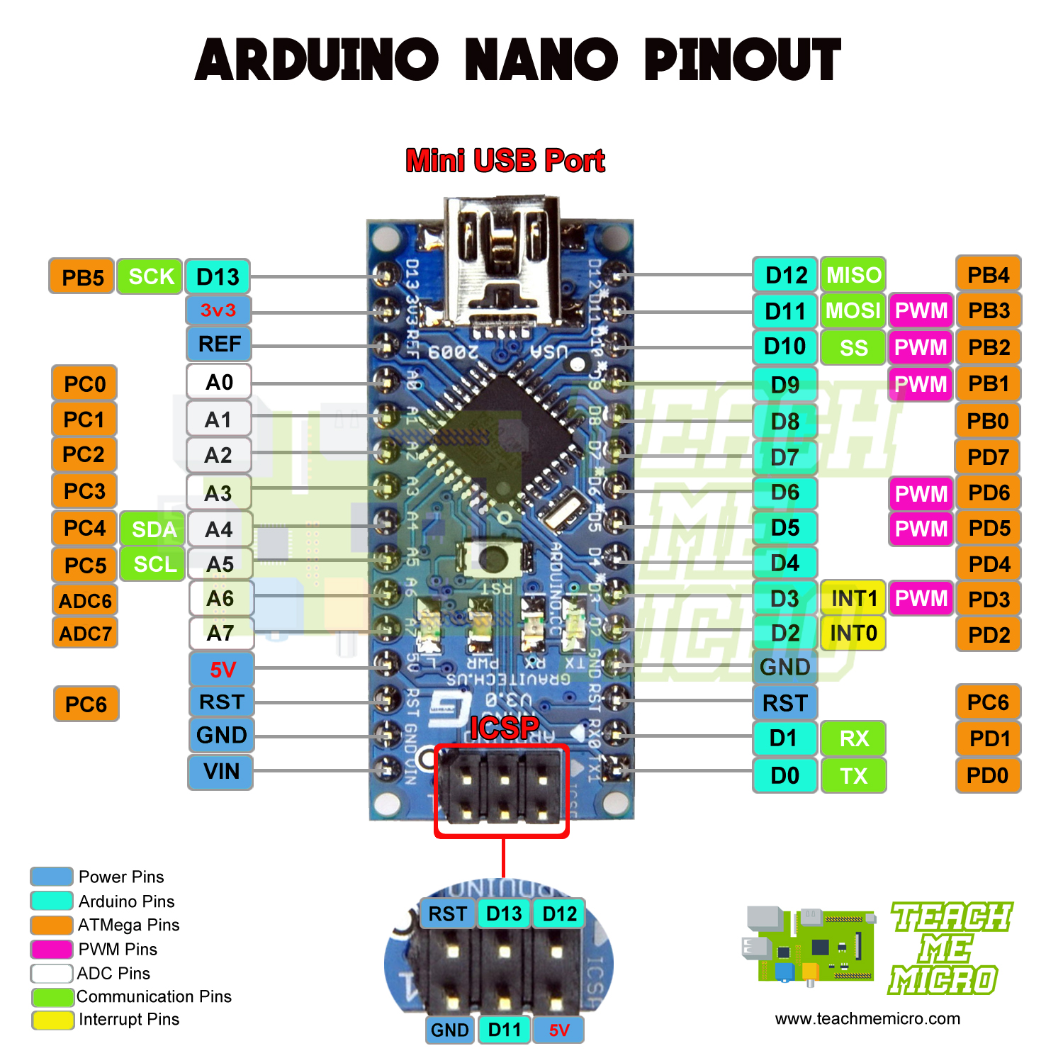
please make sure you are using a PWM pin seen here and not just an ADC analog input pin
-
\$\begingroup\$ Very Helpful!Thanks \$\endgroup\$usman shah– usman shah2020年05月27日 17:03:33 +00:00Commented May 27, 2020 at 17:03
-
\$\begingroup\$ no prob, by the way don't forget you're going to be putting 140mW of power across your fet at 20mA, so make sure it can handle that. and if the max output can't reach 20mA put a 12k pull up to +12v on your RC filter output to give yourself a little extra range \$\endgroup\$Hatman– Hatman2020年05月27日 17:33:46 +00:00Commented May 27, 2020 at 17:33
-
\$\begingroup\$ Yes I am using C945 transistor and its Collector Power Dissipation 400 mW(according to data sheet). Simulation works perfect. Is this will work practically for VFD to control the speed of motors. \$\endgroup\$usman shah– usman shah2020年05月27日 18:05:28 +00:00Commented May 27, 2020 at 18:05
-
\$\begingroup\$ no idea, that needs a new question and a lot more info \$\endgroup\$Hatman– Hatman2020年05月27日 18:57:05 +00:00Commented May 27, 2020 at 18:57