\$\begingroup\$
\$\endgroup\$
6
The LCD constantly shows nothing even though I built program sucessfully and found no error. I tried for many times in the past days but it doesn't work. I tried appling this code on PIC16F877 by replace some necessary instructions and it worked . Below is my code in assembly language:
 PROCESSOR PIC18F4520
#include <p18f4520.inc>
 CONFIG WDT=OFF
 CONFIG BOREN=OFF
 CONFIG OSC=HS
 CONFIG LVP=OFF
 CBLOCK 0x20
 COUNT, COUNT1, TEMP
 ENDC
#DEFINE RS PORTD,0
#DEFINE RW PORTD,1
#DEFINE E PORTD,2
 ORG 0X000
MAIN:
 CLRF PORTD
 CLRF TRISD
 CALL INIT_LCD
 MOVLW 'D'
 CALL SEND_DATA
 GOTO $
INIT_LCD:
 MOVLW 0X20
 CALL SEND_CMD
 MOVLW 0X28
 CALL SEND_CMD
 MOVLW 0X0E
 CALL SEND_CMD
 MOVLW 0X06
 CALL SEND_CMD
 MOVLW 0X01
 CALL SEND_CMD
 RETURN
SEND_CMD:
 MOVWF TEMP
 ANDLW 0XF0
 MOVWF PORTD
 BCF RS
 CALL ALLOW
 SWAPF TEMP,0
 ANDLW 0XF0
 MOVWF PORTD
 BCF RS
 CALL ALLOW
 CALL DELAY
 RETURN
ALLOW:
 BSF E
 NOP
 BCF E
 RETURN
SEND_DATA:
 MOVWF TEMP
 ANDWF 0XF0
 MOVWF PORTD
 BSF RS
 CALL ALLOW
 SWAPF TEMP,0
 ANDWF 0XF0
 MOVWF PORTD
 BSF RS
 CALL ALLOW
 CALL DELAY
 RETURN
DELAY:
 MOVLW 0XFF
 MOVWF COUNT
DEL:
 MOVLW 0XFF
 MOVWF COUNT1
DEC:
 DECF COUNT1,1
 BNZ DEC
 DECFSZ COUNT,1
 GOTO DEL
 RETURN
 END
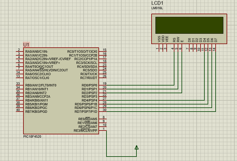
The hardward connection simulated on Proteus is below: PIC18F4520 interfacing with LCD
-
1\$\begingroup\$ So is the problem with simulated circuit in Proteus, or on a real world circuit you built? But how come you even expect it to work, because the Proteus schematic clearly omits ALL power supplies to the LCD, including the logic supply and LCD panel drive voltage. Oh and the sequence to send commands to go to 4-bit mode is also clearly wrong. \$\endgroup\$Justme– Justme2020年05月17日 16:51:04 +00:00Commented May 17, 2020 at 16:51
-
\$\begingroup\$ @Justme Thanks for your answer. I found some similar source on both google and Youtube which built this circuit like me so in my opinion, It can be omitted power supplies to LCD when simulating. Furthermore, I tried with a full circuit include conditions that you considered but it still didn't work. By the way, could you show me more clear about my fault in this code? Thanks a lot. \$\endgroup\$Thanh Nhon– Thanh Nhon2020年05月18日 05:32:48 +00:00Commented May 18, 2020 at 5:32
-
\$\begingroup\$ You can't use SEND_CMD to go into 4-bit mode, because it sends two nybbles, and the display boots into 8-bit mode, so it sees each nybble as single 8-bit commands. Since you use Proteus which most likely ignores timing, you might get away with sending the command 0X32 as the first init command. Or just to be sure, 0X33, 0X33, 0X32. \$\endgroup\$Justme– Justme2020年05月18日 07:01:39 +00:00Commented May 18, 2020 at 7:01
-
\$\begingroup\$ Pardon me if i'm misunderstanding your suggestion but are you meaning I should use 8-bit instead of 4-bit mode as before? Because the sending the command 0x32 also means initialize LCD at 8-bit mode. Meanwhile I have already sent 0X20 for LCD at the first command for 4-bit mode. \$\endgroup\$Thanh Nhon– Thanh Nhon2020年05月18日 08:25:16 +00:00Commented May 18, 2020 at 8:25
-
\$\begingroup\$ You are forgetting that the display is in 8-bit mode when it boots, so currently sending 0x20 as two nybbles makes it go out of sync. It first receives 8-bit command 0x2? which makes it go to 4-bit mode. Then the low nybble 0x0? is sent, which the display sees as first nybble of 4-bit command. So your display and code are out of sync. Sending 0x32 will send it 0x3? and 0x2? so display will be correctly expecting first nybble. \$\endgroup\$Justme– Justme2020年05月18日 09:03:11 +00:00Commented May 18, 2020 at 9:03
1 Answer 1
\$\begingroup\$
\$\endgroup\$
4
Your initialization could be more robust.
EDIT
Updated with code tested in PICDEM2+.
Please try this code:
 list n=0,c=255,r=DEC
 PROCESSOR PIC18F4520
#include <p18f4520.inc>
 CONFIG WDT=OFF
 CONFIG BOREN=OFF
 CONFIG OSC=INTIO67
 CONFIG LVP=OFF
 CBLOCK 0x20
 TEMP
 ENDC
#IFDEF TARGET_PICDEM2_PLUS
#DEFINE RS_MASK 0X10
#DEFINE RW_MASK 0X20
#DEFINE E_MASK 0X40
#DEFINE PWR_MASK 0X80
#DEFINE DATA_MASK 0X0F
#ELSE
#DEFINE RS_MASK 0X01
#DEFINE RW_MASK 0X02
#DEFINE E_MASK 0X04
#DEFINE DATA_MASK 0XF0
#ENDIF
 ORG 0X000
MAIN:
 CLRF PORTD
 CLRF TRISD
 CALL INIT_LCD
 MOVLW 'L'
 CALL SEND_DATA
 MOVLW 'C'
 CALL SEND_DATA
 MOVLW 'D'
 CALL SEND_DATA
 MOVLW ' '
 CALL SEND_DATA
 MOVLW 'T'
 CALL SEND_DATA
 MOVLW 'e'
 CALL SEND_DATA
 MOVLW 's'
 CALL SEND_DATA
 MOVLW 't'
 CALL SEND_DATA
 MOVLW ' '
 CALL SEND_DATA
 MOVLW '1'
 CALL SEND_DATA
 GOTO $
INIT_LCD:
; Wait for 15 milliseconds after power on
#IFDEF PWR_MASK
 MOVLW PWR_MASK
 MOVWF PORTD
#ENDIF
 CLRF TEMP
 MOVLW 0
POR_WAIT:
 ADDLW -1
 BTFSC STATUS,C
 BRA POR_WAIT
 DECFSZ TEMP,F
 BRA POR_WAIT
 MOVLW 0X33
 CALL SEND_CMD
 MOVLW 0X32
 CALL SEND_CMD
 MOVLW 0X28
 CALL SEND_CMD
 MOVLW 0X0E
 CALL SEND_CMD
 MOVLW 0X06
 CALL SEND_CMD
 MOVLW 0X01
 CALL SEND_CMD
 RETURN
SEND_CMD:
 MOVWF TEMP
#IF DATA_MASK == 0X0F
 SWAPF TEMP,W
#ENDIF
 ANDLW DATA_MASK
 CALL ALLOW
#IF DATA_MASK == 0X0F
 MOVF TEMP,W
#ELSE
 SWAPF TEMP,W
#ENDIF
 ANDLW DATA_MASK
 CALL ALLOW
; Longest required delay after a command write is 4 milliseconds
 MOVLW 0X40
 MOVWF TEMP
 MOVLW 0x01
CMD_WAIT:
 ADDLW -1
 BTFSC STATUS,C
 BRA CMD_WAIT
 DECFSZ TEMP,F
 BRA CMD_WAIT
 RETURN
ALLOW:
#IFDEF PWR_MASK
 IORLW PWR_MASK
#ENDIF
 MOVWF PORTD
 IORLW E_MASK
 MOVWF PORTD
 XORLW E_MASK
 MOVWF PORTD
 RETURN
SEND_DATA:
 MOVWF TEMP
#IF DATA_MASK == 0X0F
 SWAPF TEMP,W
#ENDIF
 ANDLW DATA_MASK
 IORLW RS_MASK
 CALL ALLOW
#IF DATA_MASK == 0X0F
 MOVF TEMP,W
#ELSE
 SWAPF TEMP,W
#ENDIF
 ANDLW DATA_MASK
 IORLW RS_MASK
 CALL ALLOW
; Longest required delay after a data write is 40 microseconds
 MOVLW 0XA0
DATA_WAIT:
 ADDLW -1
 BTFSC STATUS,C
 BRA DATA_WAIT
 RETURN
 END
answered May 18, 2020 at 19:31
-
\$\begingroup\$ Thanks for your help. I also tried your code but the main problem remains exist so I decided to switch to 8bit mode and got expected result. \$\endgroup\$Thanh Nhon– Thanh Nhon2020年05月19日 01:40:56 +00:00Commented May 19, 2020 at 1:40
-
1\$\begingroup\$ @STUDENTSTRANGE, I have update my answer with code tested in a PICDEM2+ so I know it should work if you connected your LCD module as you have described. \$\endgroup\$Dan1138– Dan11382020年05月19日 04:12:48 +00:00Commented May 19, 2020 at 4:12
-
1\$\begingroup\$ @STUDENTSTRANGE - Since this solution worked for you, please "accept" this answer, to effectively mark the topic as solved. See "What should I do when someone answers my question?" from the help center. Thanks. \$\endgroup\$2020年06月02日 11:00:52 +00:00Commented Jun 2, 2020 at 11:00
-
\$\begingroup\$ please be kind and accept the answer \$\endgroup\$Mike– Mike2020年06月02日 11:07:34 +00:00Commented Jun 2, 2020 at 11:07
default