I'm doing practice of bit manipulation in arduino with a 74HC595 shift register. I would like to create an algorithm that allows the binary digit to perform this way:
1 0 0 0 0 0 0 1
0 1 0 0 0 0 1 0
0 0 1 0 0 1 0 0
.
.
.
- 1 0 0 0 0 0 0 1
How can I perform this type of shifting? I don't have any fluency thinking this type of operation, I have only performed a circular shift with "an algorithm" like:
myByte = myByte*128 + myByte/2
But I don't know how to perform the output that I showed.
How can I do this? Thanks
Update1:
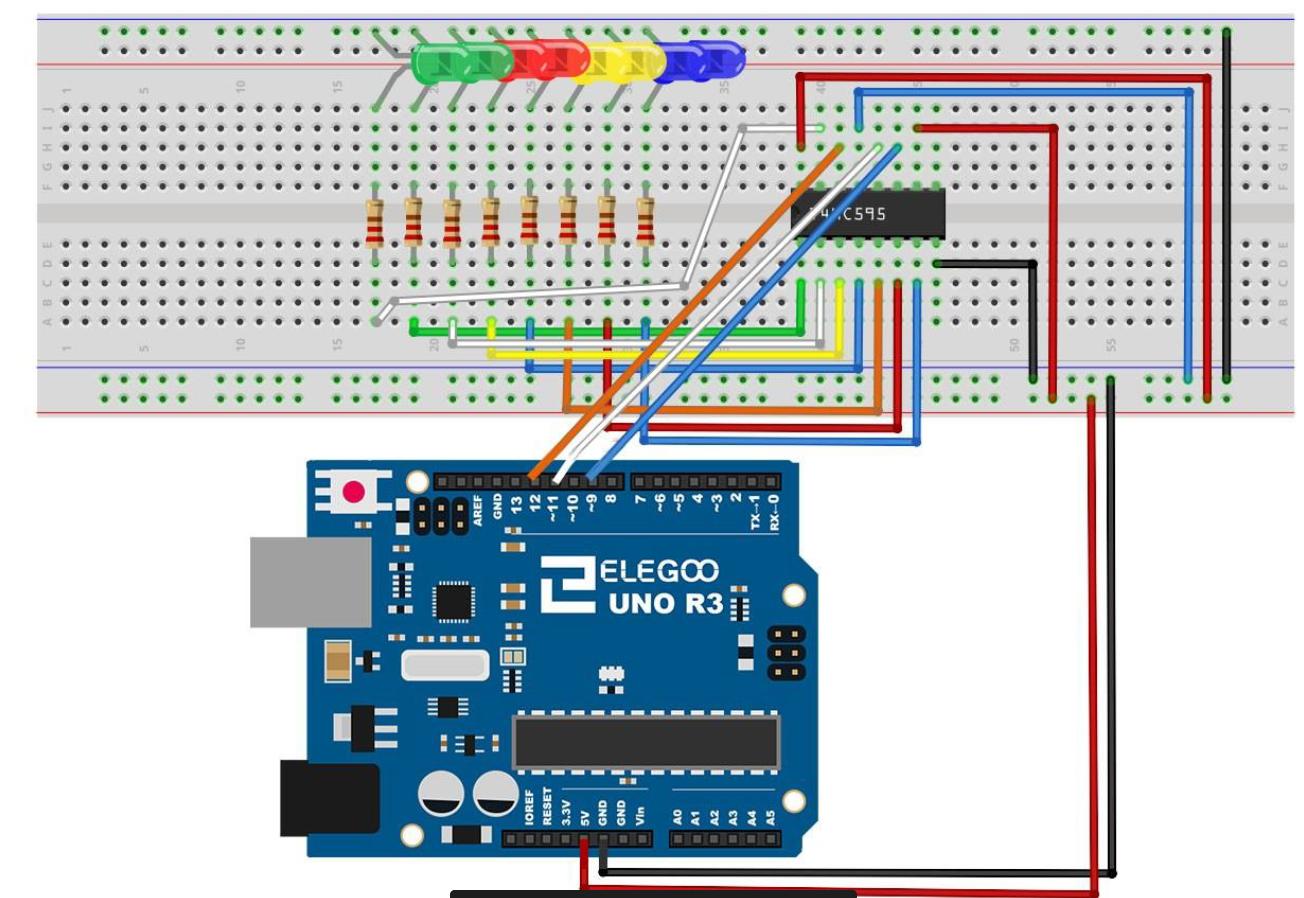
This is how is wired the circuit enter image description here
and this is the code that I use to perform a circular shift.
int latchPin = 11;
int clockPin = 9;
int dataPin = 12;
int dt = 800;
byte myByte = 0b00000001; //in BIN
void setup() {
Serial.begin(9600);
pinMode(latchPin,OUTPUT);
pinMode(dataPin,OUTPUT);
pinMode(clockPin,OUTPUT);
}
//circular shift to the left
void loop() {
digitalWrite(latchPin,LOW);
shiftOut(dataPin,clockPin,LSBFIRST,myByte);
digitalWrite(latchPin,HIGH);
Serial.print("BIN: ");
Serial.print(myByte,BIN);
Serial.print(" --> ");
Serial.print("HEX: ");
Serial.print(myByte,HEX);
Serial.print(" --> ");
Serial.print("DEC: ");
Serial.println(myByte,DEC);
myByte = myByte/128 + myByte*2; //shift by left //using MSBFIRST
delay(dt);
}
3 Answers 3
I would divide the byte in two for bitshifting then re-assemble the byte.
// First declare the variable
uint8_t myData = 0b10000001;
bool mode = 0;
void setup()
{
 // Setup Shift Register And Write the data byte as declared
}
void loop()
{
 // Copy the splitted data to two temporary variables.
 uint8_t a = myData & 0xF0;
 uint8_t b = myData & 0x0F;
 if(mode == 0)
 {
 // Bitshift the temporary variables making sure they stay within it's range
 a = a>>1 & 0xF0;
 b = b<<1 & 0x0F;
 myData = a|b;
 if(myData == 0)
 {
 //Prepare data for next cycle
 myData = 0b00011000;
 }
 }
 else
 {
 // Bitshift the temporary variables making sure they stay within it's range
 a = a<<1 & 0xF0;
 b = b>>1 & 0x0F;
 myData = a|b;
 if(myData == 0)
 {
 //Prepare data for next cycle
 myData = 0b10000001;
 }
 }
 // Write Data to Shift Register
}
This is not "The solution", there are many ways you can achieve this, this is only my approach.
I ended up using jsotola suggestion, so the code works
int latchPin = 11;
int clockPin = 9;
int dataPin = 12;
int dt = 2000;
uint8_t n1 = 128, n2 = 1;
byte myByte = 0b10000001; //in BIN
void setup() {
Serial.begin(9600);
pinMode(latchPin,OUTPUT);
pinMode(dataPin,OUTPUT);
pinMode(clockPin,OUTPUT);
}
//circular shift to the left
void loop() {
digitalWrite(latchPin,LOW);
shiftOut(dataPin,clockPin,LSBFIRST,myByte);
digitalWrite(latchPin,HIGH);
int i;
myByte = 0b10000001; //restarting the value of 129
 Serial.print("BIN: ");
 Serial.print(myByte,BIN);
 Serial.print(" --> ");
 Serial.print("HEX: ");
 Serial.print(myByte,HEX);
 Serial.print(" --> ");
 Serial.print("DEC: ");
 Serial.println(myByte,DEC);
 delay(200);
 for (int i = 0; i < 7; i++) {
 Serial.print("i: ");
 Serial.println(i);
 //int i1 = i+1;
 //int myGap = myByte - (pow(2,i)); //no need to round when it's raised to 0;
 //int firstpart = (myGap/2);
 //int secondpart = 0.5 + pow(2,i1); //because it rounds the number. (i.e --> 1.9999 = 1)
 //myByte = firstpart+ secondpart;
 myByte = (myByte - (pow(2,i)))/2 + (0.5 + pow(2,i+1));
 Serial.print("BIN: ");
 Serial.print(myByte,BIN);
 Serial.print(" --> ");
 Serial.print("HEX: ");
 Serial.print(myByte,HEX);
 Serial.print(" --> ");
 Serial.print("DEC: ");
 Serial.println(myByte,DEC);
 digitalWrite(latchPin,LOW);
 shiftOut(dataPin,clockPin,LSBFIRST,myByte);
 digitalWrite(latchPin,HIGH);
 delay(100);
 }
}
Anyway other suggestion are welcome.
How many patterns are needed? You might consider putting them in an array, and then shifting the array into the 74HC595 using SPI.transfer with pins 10 (load), 11 (MOSI), and clock (SCK).
byte dataArray[] = {
0b10000001,
0b01000010,
0b00100100,
0b00011000,
0b00100100,
0b01000010
0b10000001,
0b00000000,
}
for (x = 0; x < 8; x=x+1){
digitalWrite (ssPin, LOW);
SPI.transfer (dataArray[x]);
digitalWrite (ssPin, HIGH);
delay (1000); // to see the pattern
}
Way easier to arrange what you want. Put the array in PROGMEM if it's really big and you want to save on SRAM.
Don't forget a 0.1uF cap from the '595 VCC pin to Gnd. Will help prevent any erratic operation.
<<and>>and the bitwise OR|. All that you need. Also, off-topic here: \$\endgroup\$10000001= 128 + 1 ....01000010= 64 + 2 ....00100100= 32 + 4 .... etc .... all you need is oneforloop \$\endgroup\$