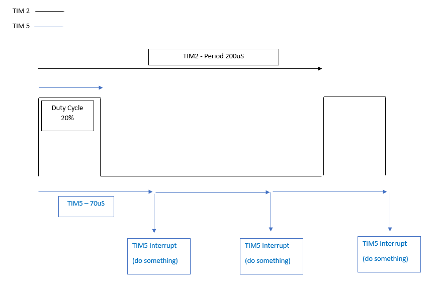
Using an stm32f411re I want to generate a PWM of 20% Duty Cycle with a period of 200uS and simultaneously I want a basic timer to be ticking in the background that sends an interrupt every 70uS (that will then enable an ADC but that's for another day). Here is a visualisation of what I want:enter image description here
enter image description here I have TIM2 generating the required PWM successfully but the issue comes when I try to add the TIM5 basic timer. Adding a second timer handler in the code for timer 5, timer 2 initialises but it doesn't generate an output. Commenting out the TIM5 handler removes the issue. Strangely commenting out all instances of when TIM5 is used and only having the handler declared at the top of my code (with the tim 5 handler doing nothing) it still causes this issue. My clock speed is 50MHz, I am using STM32CubeIDE. I'm sure it is something simple, but if anyone could take a quick look at the code so I can get TIM5 running alongside TIM2 that would be great.
Here's my main:
#include <string.h>
#include "stm32f4xx_hal.h"
#include "main.h"
void GPIO_Init(void);
void Error_handler(void);
void TIMER2_Init(void);
void TIMER5_Init(void);
void UART2_Init(void);
void SystemClock_Config_HSE(uint8_t clock_freq);
void HAL_TIM_PeriodElapsedCallback(TIM_HandleTypeDef *htim);
TIM_HandleTypeDef htimer2;
TIM_HandleTypeDef htimer5; //This line is causing the issue
UART_HandleTypeDef huart2;
uint32_t clk_freq;
int main(void)
{
 HAL_Init();
 SystemClock_Config_HSE(SYS_CLOCK_FREQ_50_MHZ);
 GPIO_Init();
 UART2_Init();
 TIMER2_Init();
 //TIMER5_Init();
 if(HAL_TIM_PWM_Start(&htimer2, TIM_CHANNEL_1) != HAL_OK)
 {
 Error_handler();
 }
// if(HAL_TIM_Base_Start(&htimer5) != HAL_OK)
// {
// Error_handler();
// }
 while(1)
 {
 clk_freq = HAL_RCC_GetHCLKFreq();
 }
 return 0;
}
/*
void HAL_TIM_PeriodElapsedCallback(TIM_HandleTypeDef *htim)
 {
 HAL_GPIO_TogglePin(GPIOA, GPIO_PIN_5);
}*/
void GPIO_Init(void)
{
 __HAL_RCC_GPIOA_CLK_ENABLE();
 GPIO_InitTypeDef ledgpio;
 ledgpio.Pin = GPIO_PIN_5;
 ledgpio.Mode = GPIO_MODE_OUTPUT_PP;
 ledgpio.Pull = GPIO_NOPULL;
 ledgpio.Speed = GPIO_SPEED_FREQ_HIGH;
 HAL_GPIO_Init(GPIOA,&ledgpio);
}
void UART2_Init(void)
{
 huart2.Instance = USART2;
 huart2.Init.BaudRate = 115200;
 huart2.Init.WordLength = UART_WORDLENGTH_8B;
 huart2.Init.StopBits = UART_STOPBITS_1;
 huart2.Init.Parity = UART_PARITY_NONE;
 huart2.Init.HwFlowCtl = UART_HWCONTROL_NONE;
 huart2.Init.Mode = UART_MODE_TX_RX;
 if ( HAL_UART_Init(&huart2) != HAL_OK )
 {
 //There is a problem
 Error_handler();
 }
}
 void TIMER2_Init(void)
{
 TIM_OC_InitTypeDef tim2PWM_Config;
 htimer2.Instance = TIM2;
 htimer2.Channel = HAL_TIM_ACTIVE_CHANNEL_1;
 htimer2.Init.Period = 10000-1; //produces a period of 200uS @ a clock of 50MHz
 htimer2.Init.Prescaler = 1;
 if ( HAL_TIM_PWM_Init(&htimer2) != HAL_OK)
 {
 Error_handler();
 }
 tim2PWM_Config.OCMode = TIM_OCMODE_PWM1;
 tim2PWM_Config.OCPolarity = TIM_OCPOLARITY_HIGH;
 tim2PWM_Config.Pulse = 2000; //Produces a D.C of 20% with a period of 200uS.
 if( HAL_TIM_PWM_ConfigChannel(&htimer2, &tim2PWM_Config, TIM_CHANNEL_1) != HAL_OK)
 {
 Error_handler();
 }
}
 /*
 void TIMER5_Init(void)
{
 htimer5.Instance = TIM5;
 htimer5.Init.CounterMode = TIM_COUNTERMODE_UP;
 htimer5.Init.Period = 64000-1;
 htimer5.Init.Prescaler = 1; //prescaler 1 means timer CNT_CLK is divided by 2. ie. CLK / 1+1
 if (HAL_TIM_Base_Init(&htimer5)!= HAL_OK)
 {
 Error_handler();
 }
}*/
my msp.c
#include "main.h"
void HAL_MspInit(void)
{
 HAL_NVIC_SetPriorityGrouping(NVIC_PRIORITYGROUP_4);
 SCB->SHCSR |= 0x7 << 16; //usage fault, memory fault and bus fault system exceptions
 HAL_NVIC_SetPriority(MemoryManagement_IRQn,0,0);
 HAL_NVIC_SetPriority(BusFault_IRQn,0,0);
 HAL_NVIC_SetPriority(UsageFault_IRQn,0,0);
}
/*void HAL_TIM_Base_MspInit(TIM_HandleTypeDef *htim )
{
 //1. Enable the clokc for TIM 5
 __HAL_RCC_TIM5_CLK_ENABLE();
 //2Enable IRQ of tim5
 HAL_NVIC_EnableIRQ(TIM5_IRQn);
 //3. set up priority for tim5 irq
 HAL_NVIC_SetPriority(TIM5_IRQn, 15, 0);
}*/
void HAL_TIM_PWM_MspInit(TIM_HandleTypeDef *htim)
{
 GPIO_InitTypeDef tim2OC_ch_gpios;
 __HAL_RCC_TIM2_CLK_ENABLE();
 __HAL_RCC_GPIOA_CLK_ENABLE();
 tim2OC_ch_gpios.Pin = GPIO_PIN_0;
 tim2OC_ch_gpios.Mode = GPIO_MODE_AF_PP;
 tim2OC_ch_gpios.Pull = GPIO_NOPULL;
 tim2OC_ch_gpios.Speed = GPIO_SPEED_FREQ_HIGH;
 tim2OC_ch_gpios.Alternate = GPIO_AF1_TIM2;
 HAL_GPIO_Init(GPIOA, &tim2OC_ch_gpios);
 HAL_NVIC_SetPriority(TIM2_IRQn,0,0);
 HAL_NVIC_EnableIRQ(TIM2_IRQn);
}
 void HAL_UART_MspInit(UART_HandleTypeDef *huart)
{
 GPIO_InitTypeDef gpio_uart;
 __HAL_RCC_USART2_CLK_ENABLE();
 __HAL_RCC_GPIOA_CLK_ENABLE();
 //2 . Do the pin muxing configurations
 gpio_uart.Pin = GPIO_PIN_2;
 gpio_uart.Mode =GPIO_MODE_AF_PP;
 gpio_uart.Pull = GPIO_PULLUP;
 gpio_uart.Speed = GPIO_SPEED_FREQ_LOW;
 gpio_uart.Alternate = GPIO_AF7_USART2; //UART2_TX
 HAL_GPIO_Init(GPIOA,&gpio_uart);
 gpio_uart.Pin = GPIO_PIN_3; //UART2_RX
 HAL_GPIO_Init(GPIOA,&gpio_uart);
 //3 . Enable the IRQ and set up the priority (NVIC settings )
 HAL_NVIC_EnableIRQ(USART2_IRQn);
 HAL_NVIC_SetPriority(USART2_IRQn,15,0);
}
int.c
#include "main.h"
extern TIM_HandleTypeDef htimer2;
//extern TIM_HandleTypeDef htimer5;
void SysTick_Handler (void)
{
 HAL_IncTick();
 HAL_SYSTICK_IRQHandler();
}
void TIM2_IRQHandler(void)
{
 HAL_TIM_IRQHandler(&htimer2);
}
/*
void TIM5_IRQHandler(void)
{
 HAL_TIM_IRQHandler(&htimer5);
}
*/
-
\$\begingroup\$ Coding issues are usually handled on another stack.exch.. while EE issues like two synchronous timers that are not harmonically related seems to be a hidden issue. 3x70us = 210us ( also no capital s for seconds) \$\endgroup\$Tony Stewart EE since 1975– Tony Stewart EE since 19752019年11月14日 19:51:37 +00:00Commented Nov 14, 2019 at 19:51
-
\$\begingroup\$ There's hundreds of posts with the stm32 tag so I thought that it wouldn't be out of place here although it's clearly an issue with the code. One timer has a period of 200us the other 70us. \$\endgroup\$ChrisD91– ChrisD912019年11月14日 20:44:22 +00:00Commented Nov 14, 2019 at 20:44
-
\$\begingroup\$ openstm32.org/forumthread6674 this person had a similar issue but I'm not sure if their solution will be helpful to you. Maybe their code will be though. \$\endgroup\$orange1234– orange12342019年11月15日 13:24:30 +00:00Commented Nov 15, 2019 at 13:24
-
\$\begingroup\$ Thanks for the link orange. The solution to that problem was simply to rebuild the project as the drivers hadn't been correctly transferred over from CubeMX. I checked out the code, can't see any noticeable differences from my own code unfortunately. \$\endgroup\$ChrisD91– ChrisD912019年11月15日 16:09:19 +00:00Commented Nov 15, 2019 at 16:09
1 Answer 1
I would be very surprised if simply adding the definition "TIM_HandleTypeDef htimer5;" would affect other code. My guess is that you or CubeMX also changed some code.
I guess the problem is in msp.c, when you initialize both timers.
Here's a stripped down example of msp.c as I use it with STM32F0:
void HAL_ADC_MspInit(ADC_HandleTypeDef* hadc) {
 if (hadc->Instance == ADC1) {
 /* Peripheral clock enable */
 __HAL_RCC_ADC1_CLK_ENABLE();
 }
}
As you see, it takes action based on the value of hadc. Your code is commented out but as written didn't check the value.
Besides, I think you need to call __HAL_TIM_CLEAR_FLAG() in the interrupt handler TIM2_IRQHandler() but I could be wrong.
-
\$\begingroup\$ I was surprised that adding the timer handler would make any difference too. I commented out the other timer5 functions as an attempt to whittle down what was causing the issue. Wilth all functions commented out, it still stops the timer 2 output. I would have thought that every new peripheral would need a new handle? I don't think that the flag needs to be cleared as the ARR (Automatic Reload Register) does it for you. I'll add in the code for checking which peripheral generated the interrupt when I'm back at my computer. \$\endgroup\$ChrisD91– ChrisD912019年11月14日 22:10:36 +00:00Commented Nov 14, 2019 at 22:10