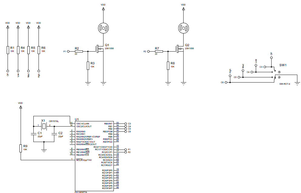
I have bread boarded the following proteus proffessional project:
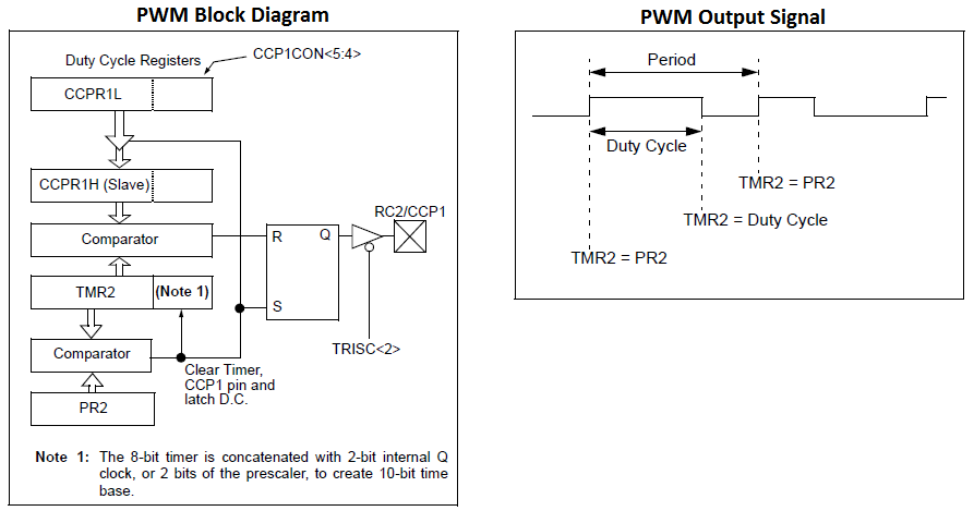
The idea is that the rotary switch controls the speed of the 2 DC fans, the high option results in 100% duty cycle, Med 75%, and Low is 50%. The tutorial I followed to configure the PWM module of the PIC16F877A gives this image taken from the IC's manual about how the PWM mode of the MCU basically works:
PWM Signal Generation: Once the PWM is configured and Timer2 is enabled, TMR2 starts incrementing depending on the prescalar. Once the TMR2 value is equal to dutyCycle(CCPR1L+CCP1CON<5:4>) the PWM pin will be pulled LOW. The timer still continues to increment till it matches with the period PR2. After which the PWM pin will be pulled HIGH and TMR2 is reset for next cycle. Source
And so I wrote some code in mikroC where I configure both CCP modules since I need a PWM signal to control the speed of two fans. Here is the snippet of code which is supposed to configure the PWM mode of these CCP registers:
TRISC.RC1 = 0;
TRISC.RC2 = 0;
CCP1CON = 0x0F; // Select the PWM mode.
CCP2CON = 0x0F;
TMR2ON = 1;
PR2 = 100; // Set the Cycle time to 100 for varying the duty cycle from 0-100
CCPR1L = 0; // By default set the dutyCycle to 0
CCPR2L = 0;
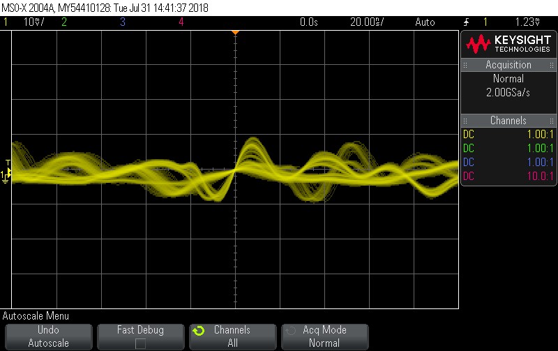
When I run the simulation it works in proteus. When I try to upload it to the MCU using my Pick kit 3 I am not getting a PWM signal on PORTC1-2. I have checked that the switch is working using a multimeter and have probed the crystal and found that it is oscillating. The switching mechanism doesn't seem to have a notable effect on the signals on PORTC1-2 apart from maybe some slight glitch when the switch position changes.
Here is a screenshot of what the signal looks like where I am supposed to be getting a PWM wave (PORTC1).
PORTC2 looks the same. Like I said I have monitored the switching mechanism, probed the crystal and the PWM ports. I can't think why this won't work when it does in simulation. Maybe somebody could help me debug this. The rest of the C code is shown here:
 int solenoid_state = 0;
 void main()
 {
 //TRISB = 0x0F; // Configure PORTB
 TRISB.RB0 = 1;
 TRISB.RB1 = 1;
 TRISB.RB2 = 1;
 TRISB.RB3 = 1;
 TRISD.RD0 = 0;
 TRISD.RD1 = 0;
 TRISC.RC1 = 0;
 TRISC.RC2 = 0;
 CCP1CON = 0x0F; // Select the PWM mode.
 CCP2CON = 0x0F;
 TMR2ON = 1;
 PR2 = 100; // Set the Cycle time to 100 for varying the duty
 cycle from 0-100
 CCPR1L = 0; // By default set the dutyCycle to 0
 CCPR2L = 0;
 //solenoid_state = 0;
 while(1){
 if(RB0_bit == 0) // Off state
 {
 delay_ms(300);
 if(RB0_bit == 0)
 {
 CCPR1L = 0;
 CCPR2L = 0;
 RD0_bit = 0;
 RD1_bit = 0;
 }
 while(RB0_bit == 0) //Do nothing until switch status changes
 {
 }
 }
 else
 {
 solenoid_state = 1;
 //RD0_bit = 1;
 //RD1_bit = 1;
 }
 while(solenoid_state == 1)
 {
 if(RB1_bit == 0) // Low state
 {
 delay_ms(300);
 if(RB1_bit == 0)
 {
 CCPR1L = 50;
 CCPR2L = 50;
 }
 while(RB1_bit == 0) //Do nothing until switch status changes
 {
 }
 }
 else if(RB2_bit == 0) // Med state
 {
 delay_ms(300);
 if(RB2_bit == 0)
 {
 CCPR1L = 75;
 CCPR2L = 75;
 }
 while(RB2_bit == 0) //Do nothing until switch status changes
 {
 }
 }
 else if(RB3_bit == 0) // High state
 {
 delay_ms(300);
 if(RB3_bit == 0)
 {
 CCPR1L = 100;
 CCPR2L = 100;
 }
 while(RB2_bit == 0) //Do nothing until switch status changes
 {
 }
 }
 else
 {
 //RD0_bit = 0;
 //RD1_bit = 0;
 solenoid_state = 0;
 }
 }
 }
 }
Any tips/hints appreciated,
Simon.
1 Answer 1
Others suspect that your problems with the real hardware lie in the part of your code that MikroC makes very hard for you to show to others.
There are the settings for the PIC configuration words and the start up initialization of the Analog to Digital Converter and Comparator function blocks.
For simple projects like the one described it is handy to disable the ADC and Comparator functions then set or clear all of the bits in the configuration words to sensible values.
Here is your code changed to compile with the free XC8 compiler from Microchip:
/*
 * file: main.c
 * target: PIC16F877A
 * compiler: XC8 v1.45
 *
 * description:
 * Configure for PWM output ib CCP1 and CCP2.
 * Selector inputs from RB0, RB1, RB2, RB3.
 *
 */
#include <xc.h>
#pragma config FOSC = HS // Oscillator Selection bits (HS oscillator)
#pragma config WDTE = OFF // Watchdog Timer Enable bit (WDT disabled)
#pragma config PWRTE = OFF // Power-up Timer Enable bit (PWRT disabled)
#pragma config BOREN = ON // Brown-out Reset Enable bit (BOR enabled)
#pragma config LVP = OFF // Low-Voltage (Single-Supply) In-Circuit Serial Programming Enable bit (RB3 is digital I/O, HV on MCLR must be used for programming)
#pragma config CPD = OFF // Data EEPROM Memory Code Protection bit (Data EEPROM code protection off)
#pragma config WRT = OFF // Flash Program Memory Write Enable bits (Write protection off; all program memory may be written to by EECON control)
#pragma config CP = OFF // Flash Program Memory Code Protection bit (Code protection off)
#define _XTAL_FREQ 20000000
int solenoid_state = 0;
void main()
{
 INTCON = 0; // disable interrupts
 ADCON1 = 0x06; // disable ADC
 CMCON = 0x07; // disable Comparators
 //TRISB = 0x0F; // Configure PORTB
 TRISBbits.TRISB0 = 1;
 TRISBbits.TRISB1 = 1;
 TRISBbits.TRISB2 = 1;
 TRISBbits.TRISB3 = 1;
 TRISDbits.TRISD0 = 0;
 TRISDbits.TRISD1 = 0;
 TRISCbits.TRISC1 = 0;
 TRISCbits.TRISC2 = 0;
 CCP1CON = 0x0F; // Select the PWM mode.
 CCP2CON = 0x0F;
 T2CON = 0x01; // Set TIMER2 prescale as 1:4
 TMR2ON = 1;
 PR2 = 99; // Set the Cycle time to 100 for varying the duty cycle from 0-100
 CCPR1L = 0; // By default set the dutyCycle to 0
 CCPR2L = 0;
 solenoid_state = 0;
 while(1)
 {
 if(PORTBbits.RB0 == 0) // Off state
 {
 __delay_ms(300);
 if(PORTBbits.RB0 == 0)
 {
 CCPR1L = 0;
 CCPR2L = 0;
 PORTDbits.RD0 = 0;
 PORTDbits.RD1 = 0;
 }
 while(PORTBbits.RB0 == 0) //Do nothing until switch status changes
 {
 }
 }
 else
 {
 solenoid_state = 1;
 //PORTDbits.RD0 = 1;
 //PORTDbits.RD1 = 1;
 }
 while(solenoid_state == 1)
 {
 if(PORTBbits.RB1 == 0) // Low state
 {
 __delay_ms(300);
 if(PORTBbits.RB1 == 0)
 {
 CCPR1L = 50;
 CCPR2L = 50;
 }
 while(PORTBbits.RB1 == 0) //Do nothing until switch status changes
 {
 }
 }
 else if(PORTBbits.RB2 == 0) // Med state
 {
 __delay_ms(300);
 if(PORTBbits.RB2 == 0)
 {
 CCPR1L = 75;
 CCPR2L = 75;
 }
 while(PORTBbits.RB2 == 0) //Do nothing until switch status changes
 {
 }
 }
 else if(PORTBbits.RB3 == 0) // High state
 {
 __delay_ms(300);
 if(PORTBbits.RB3 == 0)
 {
 CCPR1L = 100;
 CCPR2L = 100;
 }
 while(PORTBbits.RB2 == 0) //Do nothing until switch status changes
 {
 }
 }
 else
 {
 //PORTDbits.RD0 = 0;
 //PORTDbits.RD1 = 0;
 solenoid_state = 0;
 }
 }
 }
}
Perhaps all your code needs are these lines:
 INTCON = 0; // disable interrupts
 ADCON1 = 0x06; // disable ADC
 CMCON = 0x07; // disable Comparators
-
\$\begingroup\$ The problem was actually just the writing to the T2CON register. I just needed to send a byte to this register to properly configure the prescale and the post scale bits. I will post the solution later only now I have another problem where the PWM signal on the CCP1-2 pins is only 0.5 Volts-not enough to switch on the FETS. It should be at least 3.8V. No idea what is causing this problem. \$\endgroup\$burton01– burton012018年08月02日 02:41:54 +00:00Commented Aug 2, 2018 at 2:41
-
\$\begingroup\$ Most often this is some kind of circuit wiring error, next are blown FETs, lastly blown PIC outputs. Without the PIC in the circuit how much current does it take to actually drive the FET gate input to 5.0 volts? \$\endgroup\$Dan1138– Dan11382018年08月02日 03:34:04 +00:00Commented Aug 2, 2018 at 3:34
-
3\$\begingroup\$ This was a problem caused by the probe. It was a 10:1 probe and so the voltage on this pin was 5V all along. \$\endgroup\$burton01– burton012018年08月30日 06:18:50 +00:00Commented Aug 30, 2018 at 6:18
CCPR1LandCCPR2Lassignments and stick them in an area without conditions (such as right before your while loop) and comment everything else out to make sure the PWM itself is working. Then you know if you have a logic error or truly a PWM problem. \$\endgroup\$