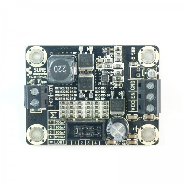
I am trying to use an Arduino + PWM to control a 100w LED using a Sure Electronics 300-3000ma buck regular - Product Here
The chip being used is LM3409
300-3000mA Buck Regulator LED Driver for 1-100W High Power LED
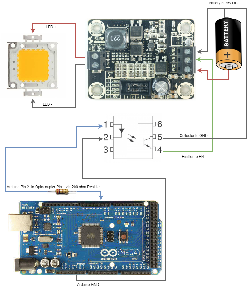
The buck regulator is powwered by an external 36v suppply to VCC + GND, and a 100W led is connected to the LED +/-.
This configuration is working fine without PWM but I can not understand how to control it with PWM from an Arduino without flicker.
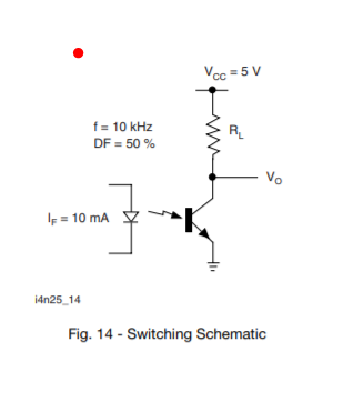
The arduino is connected to to a 4n35 Optocoupler.
The Arduino Digital Pin 2 is controlled (AnalogWrite) after reading the value of a Potentiometer (0-1024 mapped to 0-255) and is connected via a 200 Ohm Register to Pin 1 of the Optocoupler. Pin 2 of the optocouler is connected to the arduino ground.
int led = 2; // the PWM pin the LED is attached to
int last = 0;
// the setup routine runs once when you press reset:
void setup() {
 // declare pin 9 to be an output:
 Serial.begin(115200);
 pinMode(led, OUTPUT);
}
// the loop routine runs over and over again forever:
void loop() {
 int sensorValue = analogRead(A0);
 sensorValue = map(sensorValue, 0, 1023, 0, 255);
 if (sensorValue != last)
 {
 last = sensorValue;
 analogWrite(led, sensorValue);
 Serial.println(sensorValue);
 }
}
The LED buck device says that the EN pin - PWM terminal when applied with ground or suspended, full amount of current will be output and when connected with +5v or VIN, output current will be 0.
I have tested this, if I connect the 36v from the LED power supply to the EN pin the LED goes out. If I connect to ground or leave floating it runs at 100%
I do not know how to connect the other side of the Optocouler to the EN PIN properly.
I have connected pin 4 of the optocoupler (EMITTER) to the EN PIN, and connected pin 5 (COLLECTor) of the optocoupler to 36V from the VCC on the buck regulator.
This seems to work as it does go up and down in relation to changing the potentiometer.
- 0 from analogWrite on the arduino and the LED is running at 100%\
- 128 from analogWrite on the arduino and the LED is running at 50%
- 255 from analogWrite on the arduino and the LED is running at 0%
But it is not a constant brightness, it is flashing terribly and not usable.
Any help appreciated as I do not know how to move on with this.
-
\$\begingroup\$ I’m not a programmer, but is delay(100) 100 ms worth of delay, i.e. 10 Hz? Then yes, it will flicker terribly. \$\endgroup\$winny– winny2018年05月19日 08:00:28 +00:00Commented May 19, 2018 at 8:00
-
\$\begingroup\$ The delay is not needed as the arduino analogWrite() creates the PWM signal. I removed it from the code above. \$\endgroup\$chris crowe– chris crowe2018年05月19日 16:39:07 +00:00Commented May 19, 2018 at 16:39
-
\$\begingroup\$ I removed the buck regulator and use a simple LED and a resister going to ground and it seems to dim perfectly. I do not understand how the dimming is supposed to work on this driver. Also using another simple driver with separate PWM + GND worked perfectly. I just need help with these Sure Electronics drivers. \$\endgroup\$chris crowe– chris crowe2018年05月20日 05:45:42 +00:00Commented May 20, 2018 at 5:45
-
\$\begingroup\$ Show circuit diagram. \$\endgroup\$winny– winny2018年05月20日 10:17:57 +00:00Commented May 20, 2018 at 10:17
-
\$\begingroup\$ I added the components I am using to the main question. \$\endgroup\$chris crowe– chris crowe2018年05月20日 21:59:16 +00:00Commented May 20, 2018 at 21:59
1 Answer 1
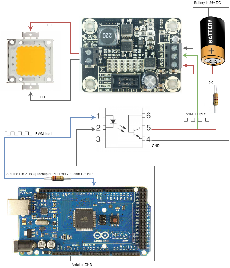
OK with the help of a colleage at my work I have now got it working.
-
\$\begingroup\$ Ah! A missing pull-up. I would not pull up to 36 V unless I knew that the EN pin was made for it. It might be over the rating for the optocoupler too. \$\endgroup\$winny– winny2018年05月22日 06:41:20 +00:00Commented May 22, 2018 at 6:41
-
\$\begingroup\$ The EN pin is rated at 45V, and the 4N35 is rated at 70V so no problem there. LM3409 - VIN, EN, UVLO to GND - 45V 4n35 - Collector emitter breakdown voltage VCEO 70 V \$\endgroup\$chris crowe– chris crowe2018年05月22日 06:44:01 +00:00Commented May 22, 2018 at 6:44