I'm trying to simulate 2bit asynchronous binary counter using D flip flops in Multisim. Here is schematic (I didn't show clock signal):
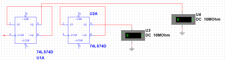
Problem is, one of flip flops is not reset (5V on Q output). When flip flops are not connected, like on schematic below, both flip flops are reset (0V on Q output).
For asynchronous counter to work properly, all flip flops should be reset before we apply clock pulse to LSB flip flop. Can I do something in Multisim for all flip flops to be reset when connected like on first schematic?
1 Answer 1
In real life these chips are not guaranteed to always start up in the same state, you need to reset them after powering on. This is what the CLR and PR pins are for. To get Q=0, you need to put PR=1 and CLR=0. Then put CLR=1 and use the chip.
Normally you could use a RC circuit to provide the reset pulse from the power supply, but in Multisim that may not be an option, so just connect a button or something so that you can reset your circuit after powering it on..