It's been years since I worked day to day with electronics and I am slowly coming back to the hobby. This is a question related to an intersection of my hobbies though: arcade stick modding and electronics.
I have a stick with 4 buttons for "functions" like "Select", "Start" and etc. The problem is I forgot 2 functions, so I am short 2 buttons.
I can solve that with a "shift" like function. So 1 button will be 'shift', 3 buttons with functions + 3 shift+button = 6 buttons.
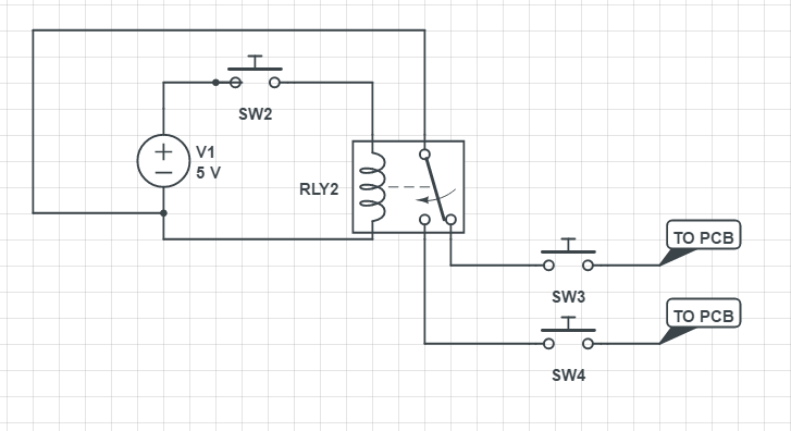
Arcade stick PCBs w/ common ground simply close the ground with a pin on the PCB to register the button activation, so if I can simulate a NC/NO relay using smaller pieces I can make it work (the shift button will just close contacts to a different pin). The thing is, I don't want to use 4 huge relays to do that. I think that means that I have to pull low on the PCB pins, I measured and have 3.3v between GND and the PCB pin, so I actually have to find a way to generate 'low pulls' from something.
I have a 5v VCC line that I can use to probably flip some transistors around, but I can't figure out if/how I can make it work with GND being the 'signal' to pass.
This would be what I would do using a relay (of course that's for a single set of buttons, not all of them, I would need 3 relays for that and I am trying to design something quick and simple).
So I bow to youse people that are way smarter and savvier on electronics to help me with that.
-
1\$\begingroup\$ What are you connecting the modified controller to? e.g. What's on the "PCB" in your question? \$\endgroup\$DrFriedParts– DrFriedParts2016年07月04日 06:00:53 +00:00Commented Jul 4, 2016 at 6:00
-
1\$\begingroup\$ Schematic or picture of board. And what is it connecting to? Is this a generic usb hid device or a custom breakout for an arcade machine? \$\endgroup\$Passerby– Passerby2016年07月04日 06:19:10 +00:00Commented Jul 4, 2016 at 6:19
-
\$\begingroup\$ There's no schematics because it's a custom controller PCB (sorry we just call it PCB on the stick lingo). I have no schematics of how the internal works. Also I can't flash a custom firmware because we don't have access to a source. Think on it like it was the PCB removed from a stock joystick. \$\endgroup\$coredump– coredump2016年07月04日 13:14:03 +00:00Commented Jul 4, 2016 at 13:14
1 Answer 1
Additional switching doesn't seem necessary.
Just receive all four buttons on your PCB, then implement the modalities in software/firmware:
A | B | C | D <-- Buttons (0=pressed, 1=open)
-------------
1 | 1 | 1 | 1 <-- Nothing pressed (idle)
0 | 1 | 1 | 1 <-- Button A
1 | 0 | 1 | 1 <-- Button B
1 | 1 | 0 | 1 <-- Button C
0 | 1 | 1 | 0 <-- Button Shift-A
1 | 0 | 1 | 0 <-- Button Shift-B
1 | 1 | 0 | 0 <-- Button Shift-C
Using solid-state switching (or a relay) will increase the number of outputs relative to the inputs. If you have a system with only 4 button inputs (because it was designed to work with 4 button controllers) where will you connect the extra signals you generated?
If your original system was designed to receive 6 buttons, but you only have 4 buttons, then you can use either the firmware approach suggested or a decoder solution (for example 74LS148) to implement the 4 -> 6 transformation.
If you'd like additional details on this approach please provide more information about what you are connecting the modified controller to and I'll elaborate appropriately.
-
\$\begingroup\$ Sorry, it is actually designed with a lot more inputs than I have buttons, I just decided (wrongly) to provide 4 face buttons for it (but the controller board has inputs for much more). I will check the decoder idea, seems to be the best way to go (I can't change the firmware). \$\endgroup\$coredump– coredump2016年07月04日 13:15:46 +00:00Commented Jul 4, 2016 at 13:15
-
\$\begingroup\$ So I think that I can solve that with an analog demux like this one sparkfun.com/products/9056 since it works kinda like a switch. I can connect all my 4 buttons to 5v and to inputs 0-4, the common I/O to GND and use the combination of buttons to connect the common to the PCB pins I need. Do I need pull-down resistors on those inputs or will it work with buttons disconnecting/setting it to 5v? \$\endgroup\$coredump– coredump2016年07月04日 18:28:28 +00:00Commented Jul 4, 2016 at 18:28
-
\$\begingroup\$ You don't need (and don't want) an analog demux. They are much more expensive and (usually) cannot pull all the way to ground/source. I will modify the answer to show you how to use a digital decoder for what you want. \$\endgroup\$DrFriedParts– DrFriedParts2016年07月04日 18:49:30 +00:00Commented Jul 4, 2016 at 18:49
-
\$\begingroup\$ New idea, using your suggestion: Connect the switches on 5v rail and to the inputs on a 74LS154 (4-to-16 decoder), since the selected port outputs low I can use it to control a PNP transistor between the joystick port and ground. I tested this on falstad and seems to work? I may need some resistor pulling up or down somewhere though. Was more or less that that you had in mind, @drfriedparts ? \$\endgroup\$coredump– coredump2016年07月05日 21:33:19 +00:00Commented Jul 5, 2016 at 21:33