|
Calvin Owens
66efbb04b4
Don't store large image files in the repository
I rewrote the history before this commit to rebase out the image files, since otherwise they'll needlessly enlarge .git forever. |
||
|---|---|---|
| include | Init | |
| prod | Init | |
| .gitignore | Init | |
| firmware.c | Init | |
| flash.sh | Init | |
| LICENSE | Init | |
| link.ld | Init | |
| Makefile | Init | |
| openocd-rpi.cfg | Init | |
| openocd.cfg | Init | |
| README.md | Don't store large image files in the repository | |
| set.sh | Init | |
| start.s | Init | |
LED Relay Clock
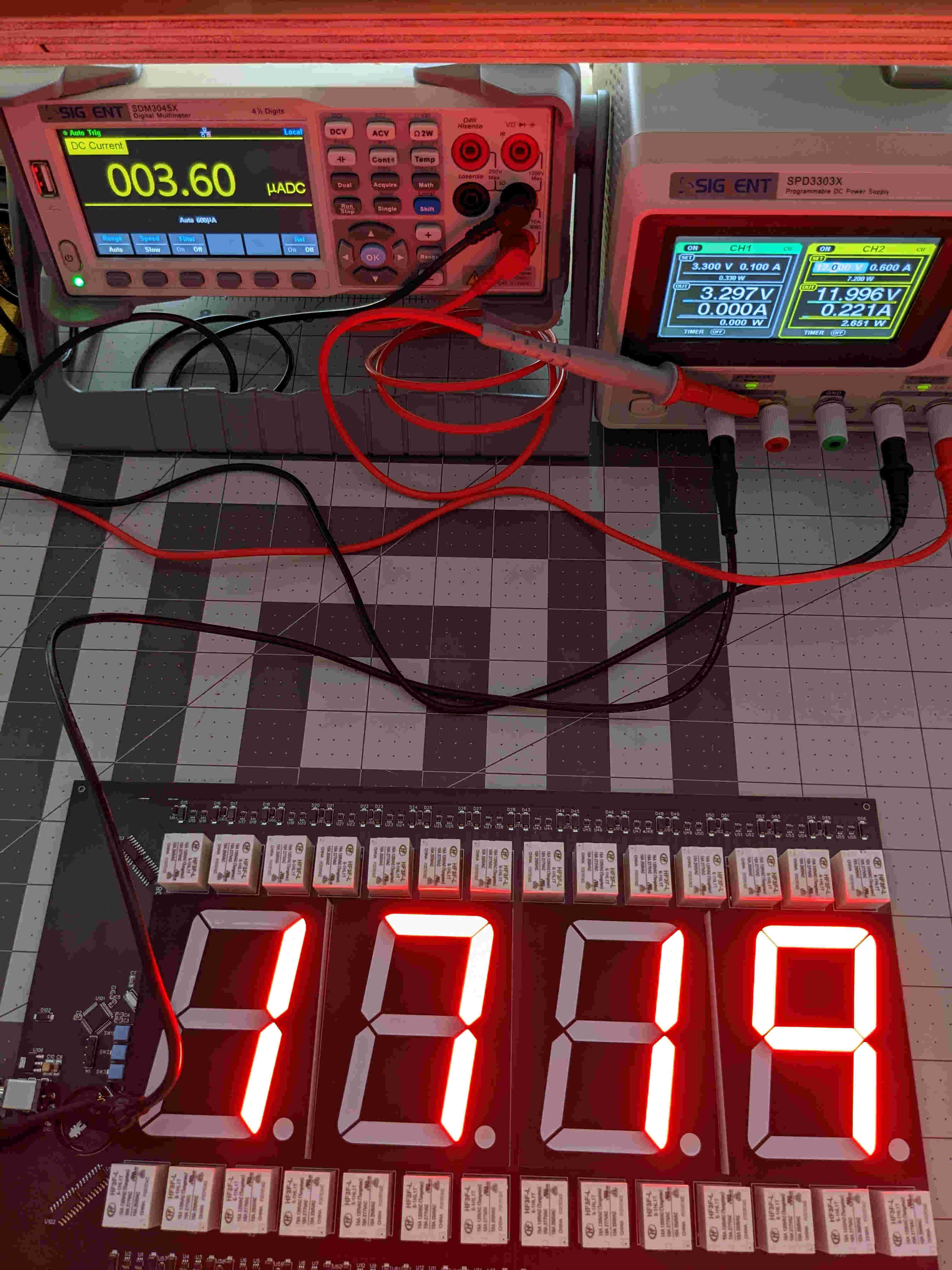
This is a wall clock which uses 28 magnetic latching relays to control the LED segments of a 4-digit display.
https://www.youtube.com/shorts/MOp447p1nEc
It's "art", or something like that...
TL;DR:
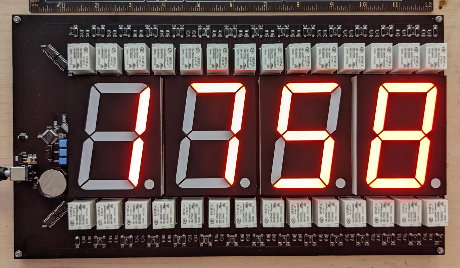
Design
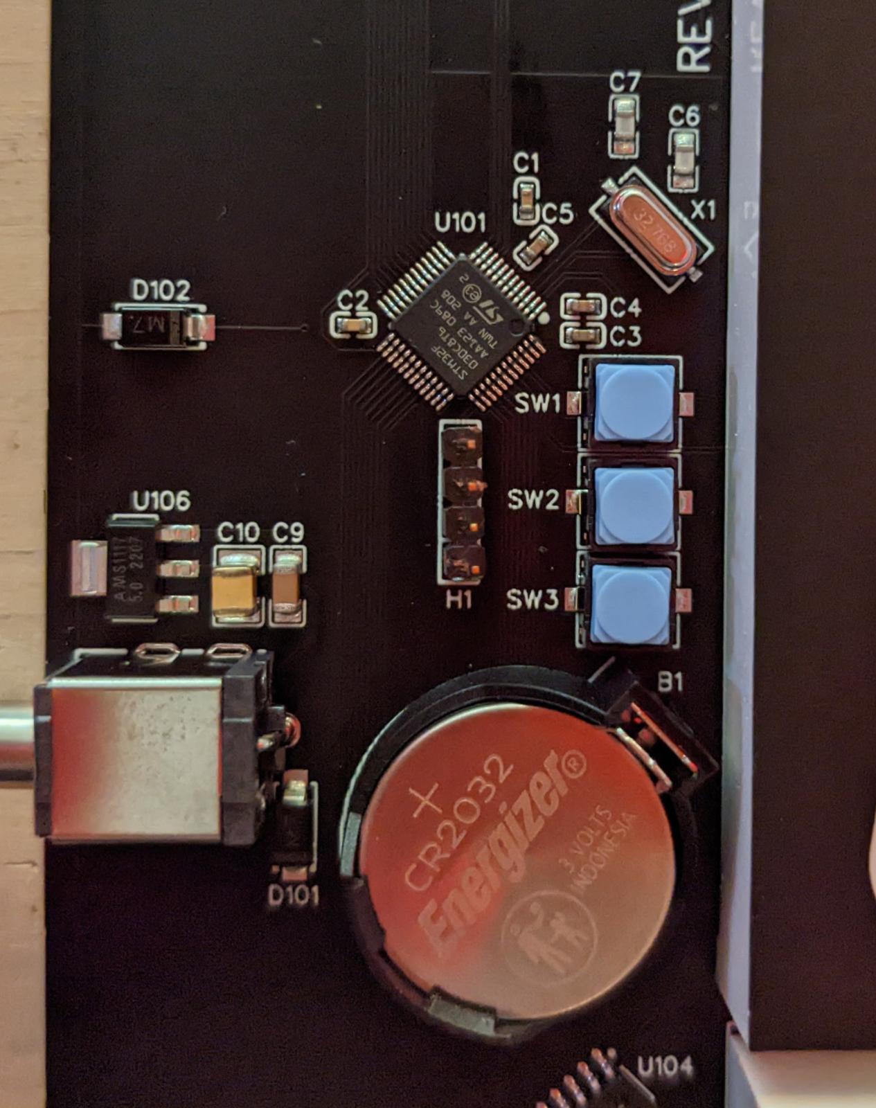
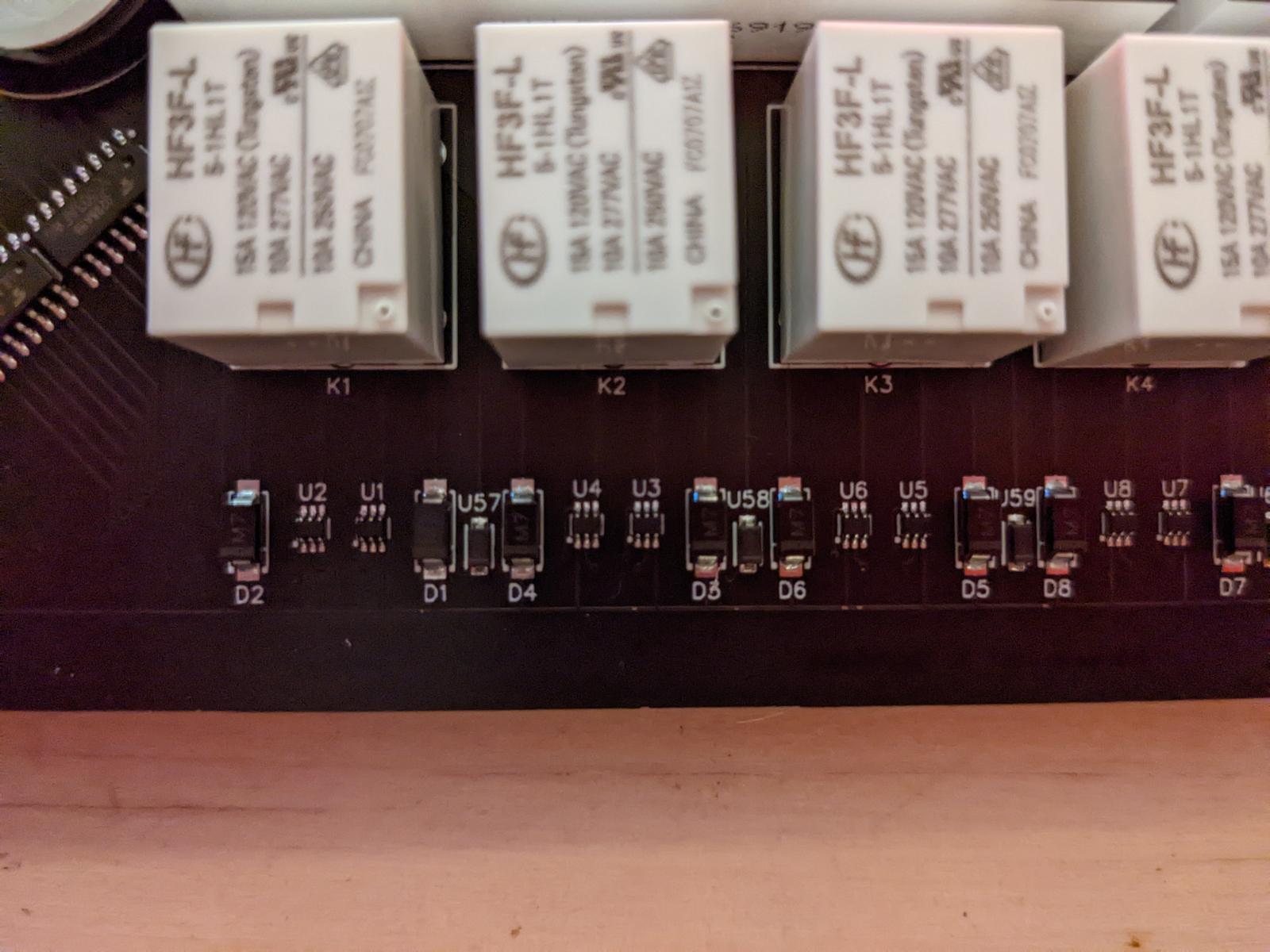
The relays are controlled by an STM32F0 ARM Cortex M0, running at 8MHz. The COILP line controls 28 pairs of oppositely wired SPDT solid state switches which function as H-bridges to set the direction of current pulse through the relay coils.
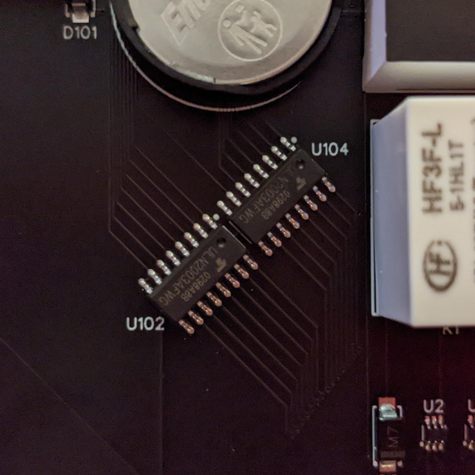
The 28 push-pull segment GPIOs are wired to bases of four Darlington array packages, which sink current from the relay coils. The 5V LDO can probably source enough current to sink them all at once, but to get the aesthetic "clicky" effect an unnecessary delay is added between them.
Latching all 28 relays every minute wastes power and makes the aesthetic effect less nice. But, since we can't read the state of the relays, it's not possible to know which ones actually need to be latched if the clock has been unplugged.
To handle this, the 5V LDO output is wired to a GPIO, and the code sets a flag and skips latching if it detects it is unplugged when it wakes up to update the clock digits. When the clock is plugged back in, the flag forces all 28 relays to be latched, so the assumption of the relay state being the prior minute's digits is always valid.
Time is kept by the built-in STM32 RTC, and the firmware is hardcoded to correct for USA/California daylight savings time through 2025.
The STM32 is powered by a CR2032 battery. The MCU draws ~1-2mA for ~200ms each minute when updating the digits, and ~4uA when sleeping. All three of the v1.2 prototypes were correct within ten minutes after 18 months of being unplugged.
Datasheets:
- ARM M0 STM32F030C8T6 (see also RM0360)
- 5V Coil Latching Relay HF3F-L/5-1HL1T
- 20mA LED Driver NSI45020T1G
- SPDT Switch BL1551B
- Darlington Array ULN2003AFWG
- 7-Segment LED SM453001L3-2
- 5V LDO AMS1117-5.0
- 32.768KHz Crystal M332768PWNAC
- Diode M7
Hardware Changelog
Rev 1.2 Changes:
- Reverse D101 (it was backwards...)
- Move SW1 from PB9 to PC13, remove C8
- Add D102 from 5V rail to PB9 for plug-in detection
- Replace U107 3.3V LDO with CR2032 battery, remove C11/C12
- Add SW2/SW3 to PF6/PF7
Rev 1.1 Changes:
- Replace the 1" LEDs with the biggest LEDs on LCSC
- Widen board to 320mm to accomodate bigger LEDs
- Replace 12V SPST relays with 5V magnetic latching relays
Ordering PCBs
I had the SMT components assembled by JLCPCB, and soldered the through-hole stuff (LED0-4, K1-28, DC1, and H1) on myself. As of August 2022, ordering five clocks costs about 60ドル/each (300ドル), and ordering two costs 75ドル/each (150ドル), including PCBs, parts, assembly, and shipping to USA west coast.
Adjustable voltage wall adapter: https://www.amazon.com/dp/B01ISM267G
Building Firmware
No external libraries are necessary: everything is included here, and can be flashed using standard open source tools.
To build on Debian/Ubuntu, run:
sudo apt install make gcc-arm-none-eabi openocd
make
To flash to the hardware, attach the ST-LINK and run:
./flash.sh
With openocd still running from the step above, set the clock by running:
./set.sh [calibration value]
Attach GDB for debugging with:
gdb-multiarch ./ledboard.elf -ex 'target extended-remote localhost:3333'
ST-LINK: https://www.amazon.com/gp/product/B01J7N3RE6
Openocd supports bitbanging SWD, but in practice it doesn't work very well. If you want to try, use openocd-rpi.cfg as a starting point.
Add -DUSE_LSI to CFLAGS if you want to use the built-in RC oscillator instead
of the LSE crystal. It is substantially less accurate, you will need to tweak
the prescaler setting (RTC->PRER) or the clock will drift by seconds per
minute.
Using the Clock
On initial boot, the clock will display hyphens and busyloop: connect an ST-LINK, and use flash.sh and set.sh to set the time per above.
The clock has three buttons (GPIOs C13, F6, F7) which are currently unused.
License
The license for the header files from STMicro can be found at include/LICENSE. Everything else is CC0 licensed, see LICENSE in this directory.
THE SOFTWARE IS PROVIDED "AS IS", WITHOUT WARRANTY OF ANY KIND, EXPRESS OR IMPLIED, INCLUDING BUT NOT LIMITED TO THE WARRANTIES OF MERCHANTABILITY, FITNESS FOR A PARTICULAR PURPOSE AND NONINFRINGEMENT. IN NO EVENT SHALL THE AUTHORS BE LIABLE FOR ANY CLAIM, DAMAGES OR OTHER LIABILITY, WHETHER IN AN ACTION OF CONTRACT, TORT OR OTHERWISE, ARISING FROM, OUT OF OR IN CONNECTION WITH THE SOFTWARE OR THE USE OR OTHER DEALINGS IN THE SOFTWARE.