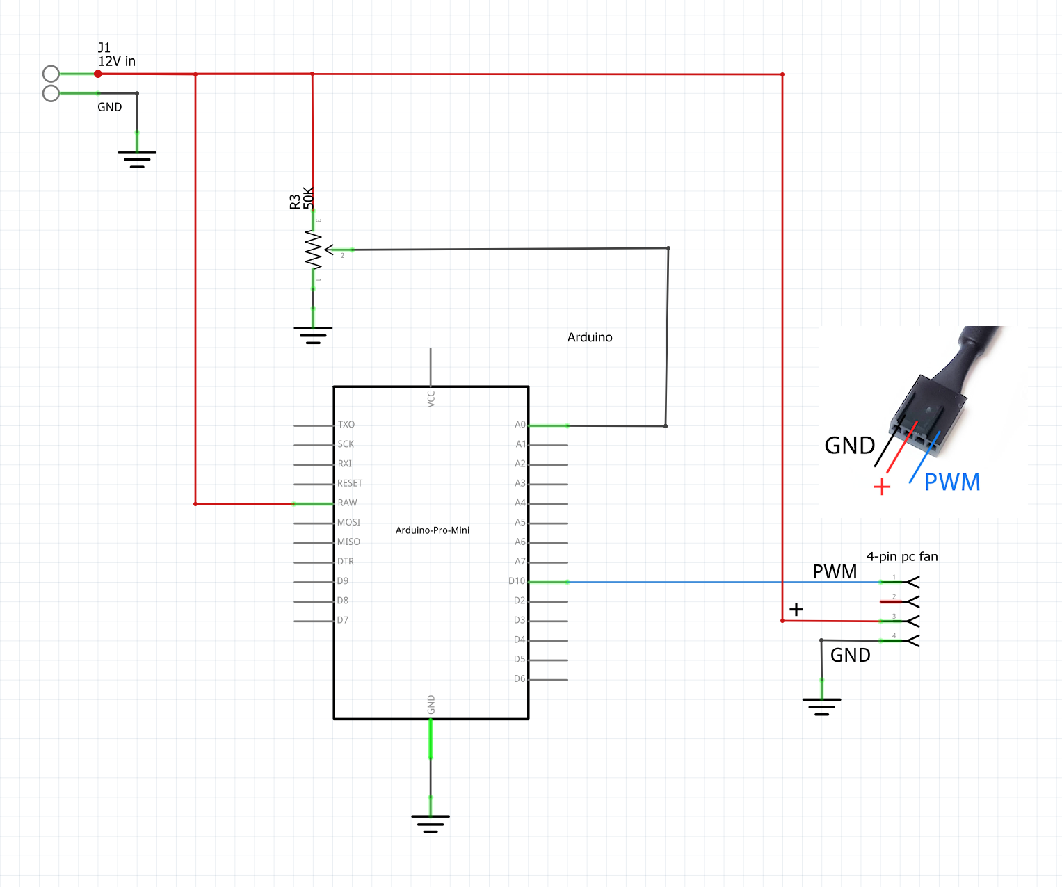
I've built the attached circuit with the following changes:
- I used Arduino Nano.
- I used 10K pot.
- 12V is connected to VIN pin (instead of RAW).
- The Arduino was connected to the PC by USB for the use of serial communication.
enter image description here I used 12V 4Pin fan (C25704-002).
Here is the code, I used:
const int analogInPin = A0; // Analog input pin that the potentiometer is attached to

 int sensorValue = 0; // value read from the pot
 int outputValue = 0; // value output to the PWM (analog out)

 void setup() {
 // Configure Timer 1 for PWM @ 25 kHz.
 TCCR1A = 0; // undo the configuration done by...
 TCCR1B = 0; // ...the Arduino core library
 TCNT1 = 0; // reset timer
 TCCR1A = _BV(COM1A1) // non-inverted PWM on ch. A
 | _BV(COM1B1) // same on ch; B
 | _BV(WGM11); // mode 10: ph. correct PWM, TOP = ICR1
 TCCR1B = _BV(WGM13) // ditto
 | _BV(CS10); // prescaler = 1
 ICR1 = 320; // TOP = 320

 // Set the PWM pins as output.
 pinMode( 10, OUTPUT);

 }

 // PWM output @ 25 kHz, only on pins 9 and 10.
 // Output value should be between 0 and 320, inclusive.
 void analogWrite25k(int value)
 {

 OCR1A = value;

 }

 void loop() {
 // read the analog in value:
 sensorValue = analogRead(analogInPin);

 // map it to the range of the analog out:
 outputValue = map(sensorValue, 0, 1023, 0, 320);

 analogWrite25k(outputValue);
I have the following questions:
- The circuit was working for couple of minutes but then I smelled the famous electronic components barbecue smell, so I disconnected the GND power line and when I did I felt that the GND line was hot, I think I fried the Arduino, Do you have an idea what can fry the Arduino?
- The Potentiometer (10K) was not sensitive, It worked only on some range of the knob, What resistance should I use?
Thanks.
-
you connected 12 V to A0jsotola– jsotola05/11/2023 03:11:07Commented May 11, 2023 at 3:11
1 Answer 1
At some point the potentiometer wiper was positioned so that A0 saw something higher than 5V and sustained long enough to do damage. Full wiper turn in one of the directions would here fry an input quickly.`
To conveniently keep using 12V and to make an input derived from it always safe, a fixed value resistor between the 12V and the upper pot leg is needed - such that: Rpot/(Rpot + Rfixed) <= 5/12 (~0.42). I.E. a safe voltage divider. For a 10K pot the fixed resistor is 13.8k.