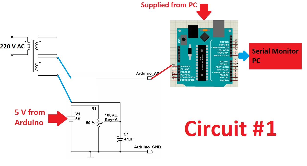
I want to display the true RMS of the main voltage using an Arduino and a MAX7219. At first, I used of circuit #1 (the following circuit) and the True RMS library. The circuit could successfully return the true RMS and print it on the Serial Monitor of thr Arduino every 0.5 s. The accuracy was acceptable. This circuit was supplied from a PC.
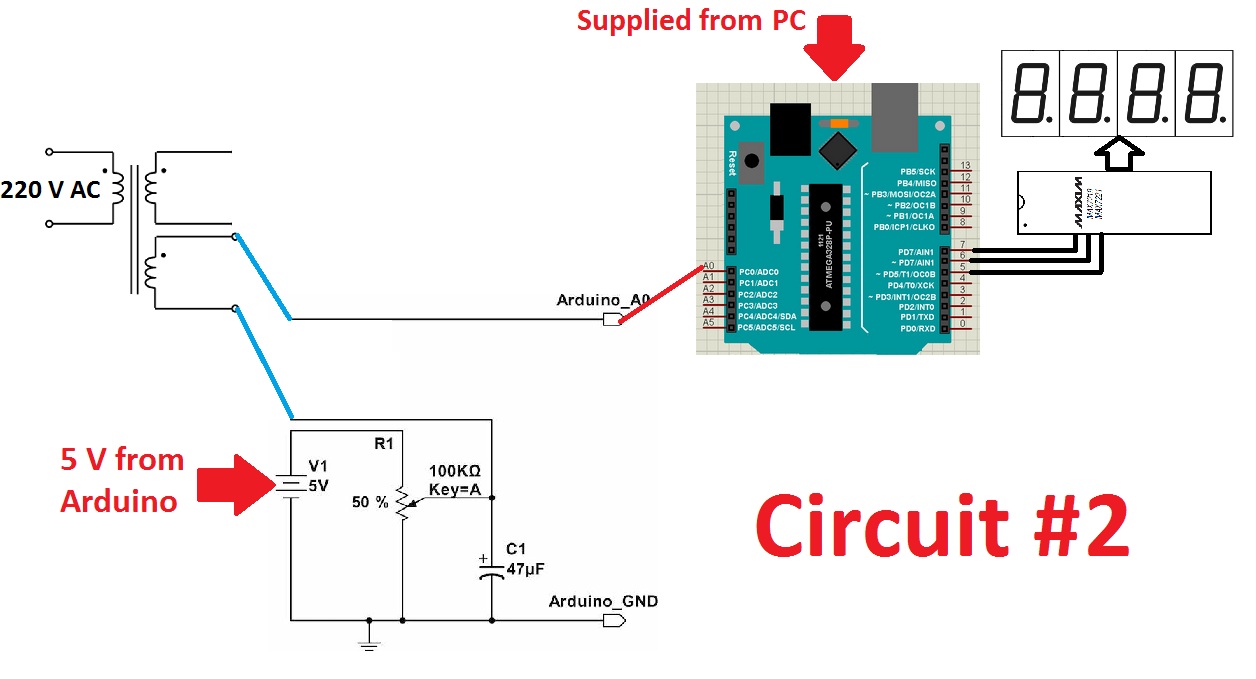
At the next step, I decided to use a MAX7219 (LedControl library) to display the true RMS voltage on a 7-segment display. For this, I used of circuit #2. I don't know what happened. The displayed voltage had variations. In circuit #1, the maximum error was 1 volt (checked by a true-RMS multimeter - for example, the voltage was 210 V and the printed voltage was 209 or 211 V). But in circuit #2, the error was up to 10 V with a fast variation. For example, the voltage was about 210 V (using multimeter) for a minute, but the displayed voltage by the Arduino was 203, then 209, then 217, then 205, then 200, then 215, ....
I also used another true-RMS multimeter to check the first multimeter. The voltage was the same value as the first one showed. The problem was that the voltage remained approximately constant, but the Arduino showed a variable voltage. I checked the supplied voltage from the PC. It doesn't have effective changes.
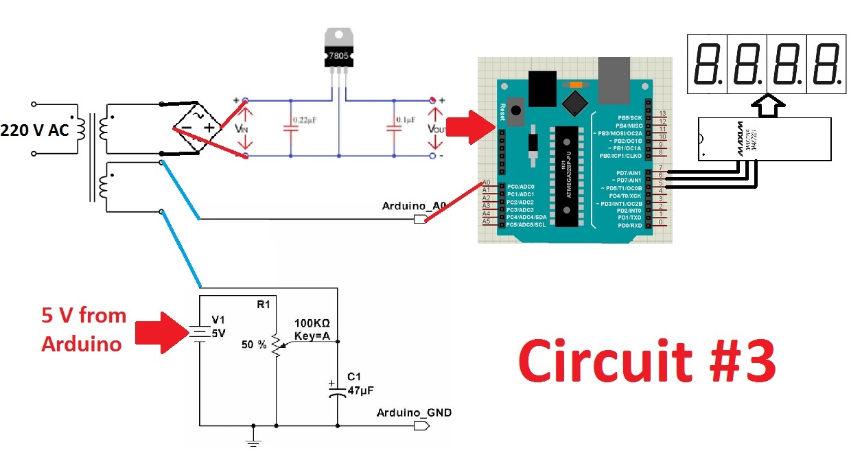
I also used of circuit #3, but I still had the same problem. It seems that the used of MAX7219 is causing the problem. What is the solution?
My code (for bi-color common anode 7-segment - I have 3 digits):
#include <TrueRMS.h>
#include <digitalWriteFast.h> // It uses digitalWriteFast only for the purpose of debugging!
 // https://code.google.com/archive/p/digitalwritefast/downloads
#define LPERIOD 1000 // 1000 loop period time in us. In this case 1.0ms
#define ADC_INPUT 0 // define the used ADC input channel
#define RMS_WINDOW 40 // rms window of 40 samples, means 2 periods @50Hz
// #define RMS_WINDOW 50 // rms window of 50 samples, means 3 periods @60Hz
#define PIN_DEBUG 4
unsigned long nextLoop;
int adcVal;
int cnt = 0;
float VoltRange = 5.00; // The full scale value is set to 5.00 Volts but can be changed when using an
 // input scaling circuit in front of the ADC.
Rms readRms; // create an instance of Rms.
// Max7219 ===============================================================
#include "LedControl.h"
int ClockPin = 5;
int CsPin = 6;
int DinPin = 7;
LedControl lc = LedControl(DinPin, ClockPin, CsPin, 1);
// 1 as we are only using 1 MAX7219
void setup() {
 Serial.begin(115200);
 pinMode(PIN_DEBUG, OUTPUT);

 // configure for automatic base-line restoration and continuous scan mode:
 readRms.begin(VoltRange, RMS_WINDOW, ADC_10BIT, BLR_ON, CNT_SCAN);
 //readRms.begin(VoltRange, RMS_WINDOW, ADC_10BIT, BLR_OFF, CNT_SCAN);
 // configure for no baseline restauration and single scan mode:
 //readRms.begin(VoltRange, RMS_WINDOW, ADC_10BIT, BLR_OFF, SGL_SCAN);
 readRms.start(); //start measuring
 nextLoop = micros() + LPERIOD; // Set the loop timer variable for the next loop interval.
 // Max7219
 // the zero refers to the MAX7219 number, it is zero for 1 chip
 lc.shutdown(0, false); // turn off power saving, enables display
 lc.setIntensity(0, 15); // 15 sets brightness (0~15 possible values)
 lc.clearDisplay(0); // clear screen
 }
// Max7219
byte board[1][8] = {
 {
 B00000000,
 B00000000,
 B00000000,
 B00000000,
 B00000000,
 B00000000,
 B00000000,
 B00000000
 }
};
// Max7219 Device
void ClearDisplay(int b, int digit) {
 for (int i=0; i<8; i++) { // It clears all segments of Digit "digit" of Device "n"
 bitClear(board[b][i], 7-digit);
 }
}
void Display() {
 for (int i=0; i<9; i++){
 lc.setRow(0, i, board[0][i]);
 }
}
// Device Digit Num Dot
void SetNum(int b, int digit, int num, int dot) {
switch(num) {
 case -2: // displays "-"
 bitClear(board[b][0], 7-digit); // seg-A
 bitClear(board[b][1], 7-digit); // seg-B
 bitClear(board[b][2], 7-digit); // seg-C
 bitClear(board[b][3], 7-digit); // seg-D
 bitClear(board[b][4], 7-digit); // seg-E
 bitClear(board[b][5], 7-digit); // seg-F
 bitSet(board[b][6], 7-digit); // seg-G
 break;
 case -1: // it clears the display
 bitClear(board[b][0], 7-digit); // seg-A
 bitClear(board[b][1], 7-digit); // seg-B
 bitClear(board[b][2], 7-digit); // seg-C
 bitClear(board[b][3], 7-digit); // seg-D
 bitClear(board[b][4], 7-digit); // seg-E
 bitClear(board[b][5], 7-digit); // seg-F
 bitClear(board[b][6], 7-digit); // seg-G
 break;
 case 0:
 bitSet(board[b][0], 7-digit); // seg-A
 bitSet(board[b][1], 7-digit); // seg-B
 bitSet(board[b][2], 7-digit); // seg-C
 bitSet(board[b][3], 7-digit); // seg-D
 bitSet(board[b][4], 7-digit); // seg-E
 bitSet(board[b][5], 7-digit); // seg-F
 bitClear(board[b][6], 7-digit); // seg-G
 break;
 case 1:
 bitClear(board[b][0], 7-digit); // seg-A
 bitSet(board[b][1], 7-digit); // seg-B
 bitSet(board[b][2], 7-digit); // seg-C
 bitClear(board[b][3], 7-digit); // seg-D
 bitClear(board[b][4], 7-digit); // seg-E
 bitClear(board[b][5], 7-digit); // seg-F
 bitClear(board[b][6], 7-digit); // seg-G
 break;
 case 2:
 bitSet(board[b][0], 7-digit); // seg-A
 bitSet(board[b][1], 7-digit); // seg-B
 bitClear(board[b][2], 7-digit); // seg-C
 bitSet(board[b][3], 7-digit); // seg-D
 bitSet(board[b][4], 7-digit); // seg-E
 bitClear(board[b][5], 7-digit); // seg-F
 bitSet(board[b][6], 7-digit); // seg-G
 break;
 case 3:
 bitSet(board[b][0], 7-digit); // seg-A
 bitSet(board[b][1], 7-digit); // seg-B
 bitSet(board[b][2], 7-digit); // seg-C
 bitSet(board[b][3], 7-digit); // seg-D
 bitClear(board[b][4], 7-digit); // seg-E
 bitClear(board[b][5], 7-digit); // seg-F
 bitSet(board[b][6], 7-digit); // seg-G
 break;
 case 4:
 bitClear(board[b][0], 7-digit); // seg-A
 bitSet(board[b][1], 7-digit); // seg-B
 bitSet(board[b][2], 7-digit); // seg-C
 bitClear(board[b][3], 7-digit); // seg-D
 bitClear(board[b][4], 7-digit); // seg-E
 bitSet(board[b][5], 7-digit); // seg-F
 bitSet(board[b][6], 7-digit); // seg-G
 break;
 case 5:
 bitSet(board[b][0], 7-digit); // seg-A
 bitClear(board[b][1], 7-digit); // seg-B
 bitSet(board[b][2], 7-digit); // seg-C
 bitSet(board[b][3], 7-digit); // seg-D
 bitClear(board[b][4], 7-digit); // seg-E
 bitSet(board[b][5], 7-digit); // seg-F
 bitSet(board[b][6], 7-digit); // seg-G
 break;
 case 6:
 bitSet(board[b][0], 7-digit); // seg-A
 bitClear(board[b][1], 7-digit); // seg-B
 bitSet(board[b][2], 7-digit); // seg-C
 bitSet(board[b][3], 7-digit); // seg-D
 bitSet(board[b][4], 7-digit); // seg-E
 bitSet(board[b][5], 7-digit); // seg-F
 bitSet(board[b][6], 7-digit); // seg-G
 break;
 case 7:
 bitSet(board[b][0], 7-digit); // seg-A
 bitSet(board[b][1], 7-digit); // seg-B
 bitSet(board[b][2], 7-digit); // seg-C
 bitClear(board[b][3], 7-digit); // seg-D
 bitClear(board[b][4], 7-digit); // seg-E
 bitClear(board[b][5], 7-digit); // seg-F
 bitClear(board[b][6], 7-digit); // seg-G
 break;
 case 8:
 bitSet(board[b][0], 7-digit); // seg-A
 bitSet(board[b][1], 7-digit); // seg-B
 bitSet(board[b][2], 7-digit); // seg-C
 bitSet(board[b][3], 7-digit); // seg-D
 bitSet(board[b][4], 7-digit); // seg-E
 bitSet(board[b][5], 7-digit); // seg-F
 bitSet(board[b][6], 7-digit); // seg-G
 break;
 case 9:
 bitSet(board[b][0], 7-digit); // seg-A
 bitSet(board[b][1], 7-digit); // seg-B
 bitSet(board[b][2], 7-digit); // seg-C
 bitSet(board[b][3], 7-digit); // seg-D
 bitClear(board[b][4], 7-digit); // seg-E
 bitSet(board[b][5], 7-digit); // seg-F
 bitSet(board[b][6], 7-digit); // seg-G
 break;
 default:
 break;
 }
 if (dot == 1) {
 bitSet(board[b][7], 7-digit); // seg-dp
 }
}
// 0-1-2-3
// Device Digit Num Dot Color
void SetNumWithColor(int b, int digit, int num, int dot, char color) {
 switch(color) {
 case 'r': // digits 0,1,2,3 are Red
 SetNum(b, digit, num, dot);
 SetNum(b, 4, -1, dot); // clears all Green segments
 SetNum(b, 5, -1, dot); // clears all Green segments
 SetNum(b, 6, -1, dot); // clears all Green segments
 SetNum(b, 7, -1, dot); // clears all Green segments
 break;
 case 'g': // digits 4,5,6,7 are Green
 SetNum(b, digit+4, num, dot);
 SetNum(b, 0, -1, dot); // clears all Red segments
 SetNum(b, 1, -1, dot); // clears all Red segments
 SetNum(b, 2, -1, dot); // clears all Red segments
 SetNum(b, 3, -1, dot); // clears all Red segments
 break;
 case 'o':
 SetNum(b, digit, num, dot); // Turns Red on
 SetNum(b, digit+4, num, dot); // Turns Green on
 break;
 default:
 break;
 }
 Display();
}
void loop() {
 adcVal = analogRead(ADC_INPUT); // read the ADC.
 // readRms.update(adcVal); // update
 digitalWriteFast(PIN_DEBUG, HIGH);
 readRms.update(adcVal); // for BLR_ON or for DC(+AC) signals with BLR_OFF
 // readRms.update(adcVal-512); // without automatic baseline restoration (BLR_OFF); substract a fixed DC offset in ADC-units here.
 digitalWriteFast(PIN_DEBUG, LOW);
 cnt++;
 if (cnt >= 1500) { // 500 = publish every 0.5s
 readRms.publish();
 float RMS=readRms.rmsVal;
 float AccRMS=RMS*128;
 int RMSout=AccRMS;
 Serial.print("Vrms=");
 Serial.print(RMSout);
 int a1=RMSout/100;
 int b1=RMSout%100;
 int a2=b1/10;
 int a3=b1%10;
 if (RMSout<200) { // Red
 SetNumWithColor(0, 0, a1, 0, 'r'); // displays a1 at digit 0
 SetNumWithColor(0, 1, a2, 0, 'r'); // displays a2 at digit 1
 SetNumWithColor(0, 2, a3, 0, 'r'); // displays a3 at digit 2
 }else if(RMSout<215){ // Orange
 SetNumWithColor(0, 0, a1, 0, 'o'); // displays a1 at digit 0
 SetNumWithColor(0, 1, a2, 0, 'o'); // displays a2 at digit 1
 SetNumWithColor(0, 2, a3, 0, 'o'); // displays a3 at digit 2
 }else{ // Green
 SetNumWithColor(0, 0, a1, 0, 'g'); // displays 1 at digit 0
 SetNumWithColor(0, 1, a2, 0, 'g'); // displays 2 at digit 1
 SetNumWithColor(0, 2, a3, 0, 'g'); // displays 3 at digit 2
 }
 Serial.print(", Vin=");
 Serial.println(RMS,4);
 // float dc=readRms.dcBias;
 // Serial.println(dc,4);
 cnt=0;
 // readRms.start(); // Restart the acquisition after publishing if the mode is single scan.

 }
 while (nextLoop > micros()); // wait until the end of the loop time interval
 nextLoop += LPERIOD; // set next loop time to current time + LOOP_PERIOD
}
// end of Measure_rms.ino
1 Answer 1
Without seeing your code it's hard to guess completely, but this is my supposition:
- The RMS measurement has to measure rapidly over a short period to capture the peak values of the AC waveform
- You are updating the display while doing the measurement
- The display updates slow down the sampling of the AC waveform giving you incorrect values.
You need to make sure that the sampling of the AC waveform happens fast enough by not doing anything else (much) during the sampling period and only displaying anything on the display when all the sampling for the current data point is done.
-
2Thank you. Before displaying, the RMS over two periods is calculated. So, updating occurs after measurement and calculation. The code is here (github.com/MartinStokroos/TrueRMS). Actually, I plotted only A0 using "Serial Plotter" of Arduino. I could see that the amplitude is obviously changing fast in circuit #2!!!! while the multimeter didn't confirm this. But for circuit #1, it didn't occur at all. Why? Does Max7219 affect the input A0 or sin wave of main voltage?soheil– soheil2022年08月10日 19:24:51 +00:00Commented Aug 10, 2022 at 19:24
-
1That's just the library and examples. It's not your code.Majenko– Majenko2022年08月10日 19:30:09 +00:00Commented Aug 10, 2022 at 19:30
-
1
-
1@soheil the answer applies for setup() too2023年01月09日 10:40:07 +00:00Commented Jan 9, 2023 at 10:40