If one wants to do quick bursts of free-running ADC conversions, should one pause and restart using:
The ADC enable bit: bitClear(ADCSRA,ADEN) & bitSet(ADCSRA,ADEN),
The interrupt enable bit bitClear(ADCSRA,ADIE) & bitSet(ADCSRA,ADIE),
The start conversion bit bitClear(ADCSRA,ADSC) & bitSet(ADCSRA,ADSC),
The auto-trigger enable bit bitClear(ADCSRA,ADATE) & bitSet(ADCSRA,ADATE),
or do you need some more complicated combination of the bits?
Here's some code where I'm trying to trigger a pulse and burst of samples and then report back to the host computer:
const int numSamples = 20;
const byte startPin = PD0; // start signal (pullup)
const byte pulsePin = PD6; // Normally low
const int pulse_us = 10 ; // output pulse length
int16_t sampleData[numSamples];
volatile int sample;
unsigned long t0, t;
// state machine:
typedef enum { STATE_NONE, // idle
 STATE_SAMPLING, // record ADC
 STATE_DONE, // report data
 } states;
// current state-machine state
volatile states state = STATE_NONE;
void setup()
{
 Serial.begin(115200);
 pinMode(startPin,INPUT_PULLUP);
 pinMode(pulsePin,OUTPUT);
 // Clear ADC
 ADCSRA = 0;
 ADCSRB = 0;
 ADMUX = 0;
 ADMUX |= (0b0000 << MUX0); // Choose ADC channel 0
 ADMUX |= (0b01 << REFS0); // Choose VCC reference voltage
 bitSet(ADMUX,ADLAR); // ADC left align ADC result into ADCH register
 // sampling rate is [ADC clock] / [prescaler] / [conversion clock cycles]
 // for Arduino Uno ADC clock is 16 MHz and a conversion takes 13 clock cycles
 //ADCSRA |= (0b101 << ADPS0); // /32 : 16M/32/13=38461Hz 26us
 //ADCSRA |= (0b100 << ADPS0); // /16 : 16M/16/13=76923Hz 13us 10 bit precision
 ADCSRA |= (0b011 << ADPS0); // /8 : 16M/8/13=153.8KHz 6.5us low precision
 //ADCSRA |= (0b010 << ADPS0); // /4 : 16M/4/13=307.6KHz 3.2us lower precision
 //ADCSRA |= (0b001 << ADPS0); // /2 : 16M/2/13=615.4Hz 1.6us bad precision
 ADCSRB |= (0b000 << ADTS0); // Choose free running trigger mode

 bitSet(ADCSRA,ADATE); // enable auto trigger mode per ADSCRB:ADTSx
 bitSet(ADCSRA,ADIE); // enable interrupts when measurement complete
 bitSet(ADCSRA,ADEN); // enable ADC
 bitSet(ADCSRA,ADSC); // start ADC measurements

}
ISR(ADC_vect) // Record samples
{
 sampleData[sample++] = ADC; // read 10bit value from ADC
 if (sample >= numSamples) {
 bitClear(ADCSRA,ADEN); // stop recording
 state = STATE_DONE;
 }
}
void report(){
 t = micros()-t0; // calculate elapsed time
 Serial.print("Sampling frequency: ");
 Serial.print((float)1000000/t);
 Serial.println(" KHz");
 for (int i = 0; i < numSamples; i++){
 Serial.print(i);
 Serial.print(' ');
 Serial.print(sampleData[i]);
 Serial.println();
 }
}
void startSampling(){
 sample = 0;
 t0 = micros();
 digitalWrite(pulsePin,HIGH);
 bitSet(ADCSRA,ADEN); // start ADC
 delayMicroseconds(pulse_us);
 digitalWrite(pulsePin,LOW);

}

void loop()
{
 switch (state){
 case STATE_NONE:
 if(digitalRead(startPin)==LOW){
 startSampling();
 state = STATE_SAMPLING;
 }
 break;
 case STATE_SAMPLING:
 break;
 case STATE_DONE:
 report();
 state = STATE_NONE;
 break;
 default:
 ;;
 }
}
Toggling ADEN was my first thought, but ADIE seems as if it would be faster, and ADSC seems cleanest, if it works to modulate free-running ADC mode. Which would be fastest and cleanest?
I have a Nano on order, but nothing available for testing right now.
1 Answer 1
After some bumbling around, several bit are important:
ADCSRA &= ~(bit(ADATE) | bit (ADSC) | bit (ADIE)); // Disable
ADCSRA |= bit(ADATE) | bit (ADSC) | bit (ADIE); // Enable
The interrupt enable bit bitClear(ADCSRA,ADIE) & bitSet(ADCSRA,ADIE), would stop the current ADC measurement from triggering an interrupt event.
The auto-trigger enable bit bitClear(ADCSRA,ADATE) & bitSet(ADCSRA,ADATE), triggers a new conversion as soon as the current one finishes.
The start conversion bit bitClear(ADCSRA,ADSC) & bitSet(ADCSRA,ADSC), is important for kicking off the first conversion.
The ADC enable bit bitClear(ADCSRA,ADEN) & bitSet(ADCSRA,ADEN), turns the ADC subsystem on and off, but there is a bit of a delay on start up.
Ultimately I left free-running automatic ADC enabled and switched the data recording on and off using the ADCSRA&bit(ADIE) as a "BURST" state variable. I think this is good enough for generic impulse-response testing:
//: ArduinoPulseADCSample.ino -- Pulse a pin and sample response on ADC
// For Arduino Uno/Nano/mega
// https://github.com/drf5n/foxyPulseInduction_Discrimination/tree/discrimination/ArduinoPulseADCSample
// Adapted from http://www.gammon.com.au/forum/?id=11488&reply=5#reply5
// and https://github.com/pedvide/ADC/tree/master/examples/analogContinuousRead
//
// This code emits a digital pulse on A1 and collects a sample of highspeed ADC from A0
// It sets up a free-running ADC to quickly record a set of ADC data in
// response to the pulse. The size of the pulse, pins, number of samples,
// speed of sampling, etc... are all configurable.
// The ADC interrupt handler controls the pulse length and filling the sample buffer
//
// Serial Commands:
//
// * Write v and press enter on the serial console to get the value
// * Write c and press enter on the serial console to check that the conversion status,
// * Write s to stop the conversions, you can restart it writing r.
// * Write r to restart the conversions.
// * Write p to emit a pulse and record a burst of values
// * Write d to see the data recorded during the burst (compatible with SerialPlotter)
// * Write m to see metadata about the sample size and interval
//
// Loopback test with a jumper or RC network between A1 and A2.
//
// Configurables:
const byte adcPin = 0; // A0 -- Pin to read ADC data from
const byte pulsePin = A1; // Next to A0 -- pin to pulse
const byte oneshot_pin = 12; // OC1B pin on Mega, controlled by Timer1
const int pulse_us = 50; // pulse duration
const int numSamples = 20; // sample set
// Change the sampling speed with the prescaler config in setup()
volatile uint16_t samples[numSamples];
volatile int sample = 0; // position in sample state variable
#define BURST (ADCSRA & bit(ADIE)) /* Sampling burst state variable */
int adcReading;
unsigned long sampleEnd;
unsigned long pulseStart, pulseEnd;
// ########## Timer1 One-shot functions
// The one shot pulses are output on Digital pin OC1B (Arduino Uno D10, Mega D12, Nano D3)
// Modified by Dave Forrest 2020年01月11日 for Timer 1
// Based on Josh Levine's Nov 23, 2015 work at https://github.com/bigjosh/TimerShot/blob/master/TimerShot.ino
// Setup the one-shot pulse generator and initialize with a pulse width that is (cycles) clock counts long
#define OSP_SET_WIDTH(cycles) (OCR1B = 0xffff-(cycles-1))
void osp_setup(uint16_t cycles) { // 1 idles, 0xffff never matches, 2-0xfffe makes pulses
 const byte prescaler = 0b010; // Choose /8 for 0.5us resolution
 // 0b001: /1, 16MHz, 62.5ns resolution, 4ms max
 // 0b010: /8, 2MHz, 0.5us resolution, 32ms max
 // 0b011: /64, 250kHz, 4us resolution, 263ms max
 // 0b100: /256, 62.5kHz 16us resolution, 1.048s max
 // 0b101: /1024, 15625Hz, 64us resolution, 4.194176s max
 TCCR1B = 0; // Halt counter by setting clock select bits to 0 (No clock source).
 // This keeps anyhting from happening while we get set up
 TCNT1 = 0x00; // Start counting at bottom.
 OCR1A = 0; // Set TOP to 0. This effectively keeps us from counting because the counter just keeps resetting back to 0.
 // We break out of this by manually setting the TCNT higher than 0, in which case it will count all the way up to MAX and then overflow back to 0 and get locked up again.
 OSP_SET_WIDTH(cycles); // This also makes new OCR values get loaded frm the buffer on every clock cycle.
 TCCR1A = 0b11 << COM1B0 | 0b11 << WGM10; // OC1B=Set on Match, clear on BOTTOM. Mode 15 Fast PWM.
 TCCR1B = (0b11 << WGM12) | (prescaler << CS10); // Start counting now. WGM 15=0b1111 to select Fast PWM mode
 // Setup the OC1B pin for one-shot output:
 //DDRB |= _BV(2); // Uno Set pin to output (Note that OC1B = GPIO port PB2 = Arduino Uno Digital Pin 10)
 DDRB |= _BV(6); // Mega Set pin to output (Note that OC1B = GPIO port PB6 = Arduino Mega Digital Pin 12)
 //DDRD |= _BV(3); // Nano Set pin to output (Note that OC1B = GPIO port PD3 = Arduino Nano Digital Pin 3)
}
// Setup the one-shot pulse generator to idle:
void osp_setup() {
 osp_setup(1); // 1 puts it in idle mode, 0xffff never triggers, 2-0xfffe produces pulses.
}
// Macro to Fire a one-shot pulse. Use the most recently set width.
#define OSP_FIRE() (TCNT1 = OCR1B - 1)
// Macro to Test there is currently a pulse still in progress
#define OSP_INPROGRESS() (TCNT1>0)
// Macro to Fire a one-shot pulse with the specififed width.
// Order of operations in calculating m must avoid overflow of the unint16_t.
// TCNT2 starts one count lower than the match value because the chip will block any compare on the cycle after setting a TCNT.
#define OSP_SET_AND_FIRE(cycles) {uint16_t m=0xffff-(cycles-1); noInterrupts();OCR1B=m;TCNT1 =m-1;interrupts();}
// ########## End of Timer1 One-shot functions
ISR(TIMER1_OVF_vect) { //When overflow...
 // OCRA1=ICR1; // Constant off in WGM 14, COM1A1:0==0b11
 TCCR1B &= ~(0b111 << CS10) ; //turn off clock
}
//######### ADC Bit-bang for free-running capture of A0
void adc_setup_freerunning(const byte adcPin){
 // set the analog reference (high two bits of ADMUX) and select the
 // channel (low 4 bits). this also sets ADLAR (left-adjust result)
 // to 0 (the default).
 ADMUX = bit (REFS0) | (adcPin & 0x07);
 // Set the ADC ADPSx prescaler flags to control sampling speed/accuracy
 ADCSRA &= ~(bit (ADPS0) | bit (ADPS1) | bit (ADPS2)); // clear prescaler bits
 //ADCSRA |= 0b001 << ADPS0; // 2 5 bit,
 //ADCSRA |= 0b010 << ADPS0; // 4 6 bit, 5.36us
 //ADCSRA |= 0b011 << ADPS0; // 8 9 bit, 6.51us
 ADCSRA |= 0b100 << ADPS0; // 16 10 bit, 13us
 //ADCSRA |= 0b101 << ADPS0; // 32 10 bit, 26us
 //ADCSRA |= 0b110 << ADPS0; // 64 10 bit, 52us
 //ADCSRA |= 0b111 << ADPS0; // 128 10 bit, 104us
 //enable automatic conversions, start them and interrupt on finish
 //ADCSRA |= bit(ADATE) | bit (ADSC) | bit (ADIE);
 ADCSRA |= bit(ADATE) | bit (ADSC) ;
}
void setup ()
{
 Serial.begin (115200);
 //pinMode(pulsePin, OUTPUT);
 osp_setup(); // Config Mega Digital 12 for oneshot output
 adc_setup_freerunning(adcPin);
} // end of setup
// ADC complete ISR
ISR (ADC_vect) // Store ADC burst values
{
 if (sample >= numSamples) // watch off-by-one
 {
 ADCSRA &= ~bit(ADIE); // end of sampling burst so stop interrupting
 return;
 }
 // Handle samples
 samples[sample++ ] = ADC;
 //if ( sample == 0){
 // OSP_SET_AND_FIRE(pulse_us * 2); //
 //}
} // end of ADC_vect
void loop ()
{
 char c;
 char buff[80];
 unsigned long sampleDuration;
 unsigned long pulseDuration;
 // if last reading finished, process it
 // if we aren't taking a reading, start a new one
 if (Serial.available()) {
 c = Serial.read();
 switch (c) {
 case 'c': // Converting?
 Serial.print("ADCSRA: ");
 Serial.println(ADCSRA, BIN);
 break;
 case 's': // stop conversions
 ADCSRA &= ~(bit (ADSC) | bit (ADIE));
 break;
 case 'r': // restart conversions
 ADCSRA |= bit (ADSC) | bit (ADIE);
 break;
 case 'v':
 adcReading = ADC;
 Serial.print(adcReading);
 Serial.print(' ');
 Serial.print((0.5 + adcReading) * 5.0 / 1024, 4);
 Serial.println(" V");
 break;
 case 'm':
 {
 unsigned long sampleDuration = sampleEnd - pulseStart;
 unsigned long pulseDuration = pulseEnd - pulseStart;
 Serial.print("# Pulse: ");
 Serial.print(pulseDuration);
 Serial.print("us and ");
 Serial.print(numSamples);
 Serial.println(" samples.");
 Serial.print("# Time: ");
 Serial.print(sampleDuration);
 Serial.print("us burst of ");
 Serial.print(numSamples);
 Serial.print(" samples at ");
 Serial.print(1.0 * (unsigned long)(sampleEnd - pulseStart) / numSamples);
 Serial.println("us/sample");
 sprintf(buff, " sampleEnd, pulseEnd, pulseStart %02lu : %02lu : %02lu \n", sampleEnd, pulseEnd, pulseStart);
 Serial.print(buff);
 break;
 }
 case 'p': // start pulse
 sample = 0; // reset sample SV
 pulseStart = micros();
 OSP_SET_AND_FIRE(pulse_us * 2); // pulse outside ISR
 ADCSRA |= bit(ADIF) | bit(ADIE); // clear existing ADInterruptFlag and enable ADC Interrupts
 while(BURST); // block until burst done
 sampleEnd = micros(); // Record times
 pulseEnd = pulseStart + pulse_us;
 break;
 case 'D':
 case 'd': {// report Data
 sampleDuration = sampleEnd - pulseStart;
 for (int ii = 0 ; ii < numSamples ; ii++) {
 if (c == 'D') {
 Serial.print(ii * sampleDuration / numSamples);
 Serial.print(' ');
 }
 Serial.println(samples[ii]);
 }
 }
 break;
 case ' ':
 case '\n':
 case '\r':
 break;
 case 'h':
 case '?':
 default:
 {
 Serial.println("\nArduinoPulseADCSample.in -- Pulse A1 and read a burst of samples from A0\n"
 "based on serial commands");
 Serial.println("# https://github.com/drf5n/foxyPulseInduction_Discrimination/tree/discrimination/ArduinoPulseADCSample\nCommands: [vcsrpdm] ?");
 Serial.println("Commands:\n"
 "p: Pulse -- Start a pulse cycle on A1 and record data on A0\n"
 "d,D: Data -- Dump the data from the last pulse\n"
 "m: Metadata -- Print the length of pulse, number of samples and rate\n"
 "v: Voltage -- Conver voltage on A0\n"
 "c: Converting? -- show ADCSSRA register\n"
 "h?: Help -- Print this\n"
 );
 }
 break;
 ;;
 }
 }
 // do other stuff here
} // end of loop
This is the output from the p,m,d commands with a jumper connecting pin 12 to A0 with the /16 prescaler:
# Pulse: 50us and 20 samples.
# Time: 276us burst of 20 samples at 13.80us/sample
 sampleEnd, pulseEnd, pulseStart 19270968 : 19270742 : 19270692
0
1020
1023
1023
1023
3
0
0
0
0
0
0
0
0
0
0
0
0
0
0
And again with the /8 prescaler. 7.2us/sample or 139Ksamples/sec for 8-9bits isn't bad:
# Pulse: 50us and 20 samples.
# Time: 144us burst of 20 samples at 7.20us/sample
 sampleEnd, pulseEnd, pulseStart 4229952 : 4229858 : 4229808
0
792
1020
1022
1022
1020
1022
1022
1022
305
3
0
0
0
0
0
0
0
0
0
ArduinoPulseADCSample.in -- Pulse A1 and read a burst of samples from A0
based on serial commands
# https://github.com/drf5n/foxyPulseInduction_Discrimination/tree/discrimination/ArduinoPulseADCSample
Commands: [vcsrpdm] ?
Commands:
p: Pulse -- Start a pulse cycle on A1 and record data on A0
d,D: Data -- Dump the data from the last pulse
m: Metadata -- Print the length of pulse, number of samples and rate
v: Voltage -- Conver voltage on A0
c: Converting? -- show ADCSRA register
h?: Help -- Print this
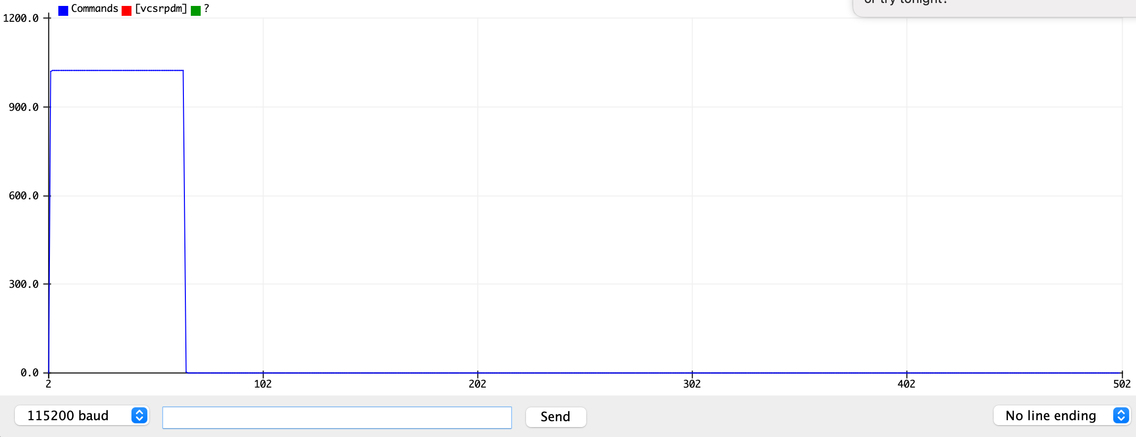
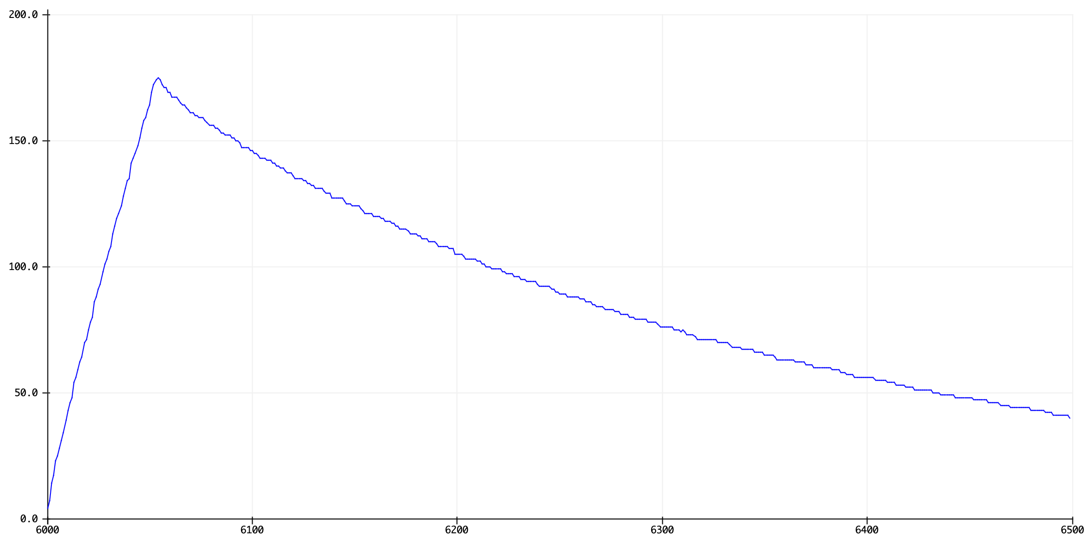
Here's an R-C pulse-decay trace on the Serial Plotter with a 22K resistor across A0&12 and a 22uF capacitor from GND to A0.
-
Re "I left free-running automatic ADC enabled and switched the data recording on and off.": I think you could do that by toggling just
ADIE, without touchingADSC. Maybe clear the interrupt flag when settingADIE, to avoid getting an interrupt from the last conversion of the previous burst.Edgar Bonet– Edgar Bonet2022年01月10日 19:39:37 +00:00Commented Jan 10, 2022 at 19:39 -
@EdgarBonet -- With the
ADIF=1trick,ADCSRA |= bit(ADIF) | bit(ADIE)would clear any pending interrupt and enable future interrupts. Sounds good. I could then use theADCSRA & bit(ADIE)instead ofburstas my "sampling" state variable and save a test. I've been tweaking things to get down to the 13us/sample threshold that I can get for the ADPS2:0=0b100 /16 1MKz speed that has full 10bit accuracy, but I haven't trimmed the ISR down enough for the /8 clock. I like the pulse control in the ISR for the sync in my use case, but it's sloppy. Maybe pulse onsamplevs micros() state var?Dave X– Dave X2022年01月11日 15:30:15 +00:00Commented Jan 11, 2022 at 15:30 -
... The pulse length control is sloppy because the pulse is started out of sync with the sampling, and finishes in sync with the sampling. I like the end synchronization with the samples for my particular application, but it would be nicer to configure a timer as a one-shot and trigger it in the ISR when the
sample == 0, then you could get higher resolution pulse lengths with both the start and end of the pulse synced with the sampling. Maybe it could reach 6.5us/sample with 8-9 bit resolution.Dave X– Dave X2022年01月11日 15:44:00 +00:00Commented Jan 11, 2022 at 15:44
sampleback to zero, when you want to start recording a new set of measurements.