UPDATE: The LCD will light up only when the all my components are located in the bottom right of the breadboard. Why am I not able to use the entire breadboard for my circuit?
I am trying to display data from a temperature and humidity sensor on the serial monitor and the liquid crystal display.
I am using :
- Arduino Uno R3
- I2C 16x2 LCD Module
- 3 pin DHT11 sensor
Here is my code :
#include <dht.h> // initialize the digital temperature and humidity sensor library ("DHTlib")
#include <LiquidCrystal_I2C.h> // initialize the liquid crystal display library ("LiquidCrystal I2C")
#include <Wire.h> // intialize the wire library
/* the first parameter is the I2C address
 * the second parameter is how many columns are on your screen
 * the third parameter is how many rows are on your screen
*/
LiquidCrystal_I2C lcd(0x27, 16, 2);
dht DHT; // create a handle to call functions from the sensor library
#define DHT11_PIN 7 // assign a digital pin number to the sensor
float TempC; // create a variable to store temperature in celsius
float TempF; // create a variable to store temperature in fahrenheit
float Humi; // create a variable to store humidity
void setup()
{
 lcd.init(); // initialize liquid crystal display
 lcd.backlight(); // turn on the backlight of the lcd
 pinMode(DHT11_PIN,INPUT); // configure the pin for the sensor as an input for reading the data
 Serial.begin(9600); // set data rate in bits per second for serial data transmission
}
void loop()
{
 // collect sensor data
 int chk = DHT.read11(DHT11_PIN); // store sensor data in a variable
 TempC = DHT.temperature; // store temperature in Celsius
 TempF = 9 / 5 * TempC + 32; // store temperature in Fahrenheit
 Humi = DHT.humidity; // store relative humidity as a percentage
 // display sensor data on LCD
 lcd.setCursor(0,0); //tell the screen to write on the top row
 lcd.print("T: ");
 lcd.print(TempC); // print the temperature in Celsius
// lcd.print(TempF); // print the temperature in Fahrenheit
 lcd.print((char)223); // print the degree symbol
 lcd.print(" C");
// lcd.print(" F");
 lcd.setCursor(0,1); // tell the screen to write on the bottom row
 lcd.print("H: ");
 lcd.print(Humi); // print the humidity
 lcd.print(" %");
 // display sensor data on the serial monitor
 Serial.print("Temperature = ");
 Serial.print(TempC); // print the temperature in Celsius
// Serial.print(TempF); // print the temperature in Fahrenheit
 Serial.print("\xc2\xb0"); // print the degree symbol
 Serial.println(" C");
// Serial.println(" F");
 Serial.print("Humidity = ");
 Serial.print(Humi); // print the humidity
 Serial.println(" %");
 delay(2000); //delay fetching the next sensor values for 2 seconds
}
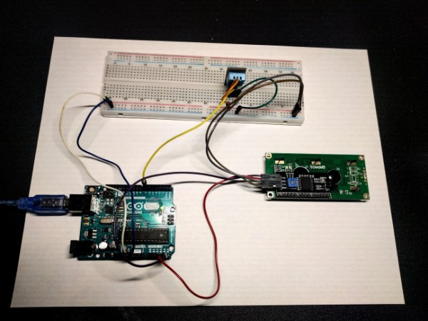
My jumper wires are connected as follows:
- DHT plus → red plus row
- DHT middle → digital pin 7
- DHT minus → blue minus row
- LCD GND → blue minus row
- LCD VCC → red plus row
- LCD SDA → analog pin A4
- LCD SCL → analog pin A5
- Red plus row → 5V pin
- Blue minus row → GND pin
Dev DhruvDev Dhruv
-
Do you not see a breadboard, an arduino board, a liquid crystal display, a sensor, and jumper wires all hooked up?Dev Dhruv– Dev Dhruv2021年04月02日 05:35:33 +00:00Commented Apr 2, 2021 at 5:35
-
The picture is unusable, dark and low resolution. Pin names and wire paths are not clearly visible. These allow others to try to identify your problem and it would be a good idea to put some more effort into getting them across clearly. It might also be a good idea to describe your setup in text (such as which pins are connected to which other pins).StarCat– StarCat2021年04月02日 06:24:19 +00:00Commented Apr 2, 2021 at 6:24
-
Btw, it looks like there’s nothing connected to the (I2C) SDA and SCL pins on your Arduino, but it’s hard to make out. There’s also no way to see if the power pins of your LCD are properly connected.StarCat– StarCat2021年04月02日 06:31:21 +00:00Commented Apr 2, 2021 at 6:31
-
All right, I put a new picture, and I explained the setup. Is there an error in my code or in my circuit?Dev Dhruv– Dev Dhruv2021年04月02日 06:31:56 +00:00Commented Apr 2, 2021 at 6:31
-
1Did you try moving the knob on the I2C 16x2 LCD Module for changing the contrast?Michel Keijzers– Michel Keijzers2021年04月02日 07:27:09 +00:00Commented Apr 2, 2021 at 7:27
1 Answer 1
Your breadboard is one of those which have the power/GND lines interrupted between columns 31 and 33. I also once fell into this trap. If you look closely, you see that the blue and red lines are interrupted in the middle of the board. Just put wires between these pins to bridge the gap.
lang-cpp