I'm trying to use a cheap keyboard with 37 keys as a MIDI controller by reading the multiplexed keys with an Arduino nano. The keys are grouped in six groups with a max of 8 keys per group. Which results in my setup of 8 digital INPUTS which are pulled HIGH, and 6 OUTPUTS, which are pulled LOW, when reading that group of keys. This works great when I only have 3 groups in my loop. However whenever I add another group it does not work anymore. It doesn't matter which groups are activated.
One group reading looks like this:
digitalWrite(A0, LOW);
for (byte j = 12; j > 4; j--)
{
 uint8_t note = offset + 20 + (12-j);
 uint8_t key_state = digitalRead(j);
 if ( (key_state == 0) && (notes_pressed[note] == 1) )
 {
 notes_pressed[note] = 0;
 Serial.write(note + 100);
 } else if ( (key_state == 1) && (notes_pressed[note] == 0) )
 {
 notes_pressed[note] = 1;
 Serial.write(note);
 }
}
digitalWrite(A0, HIGH);
With A0 being the group pin.
I think this has to do with the pins not being able to be pulled low as quickly because of weak output drivers or something similar. Unfortunately I don't have an oscilloscope to check the levels. I have added delays to ensure the levels have settled when the reading occurs but to no avail.
Edit: Schematic is pretty much just this. The diodes in the keyboard I left out, but they are there as necessary: schematic
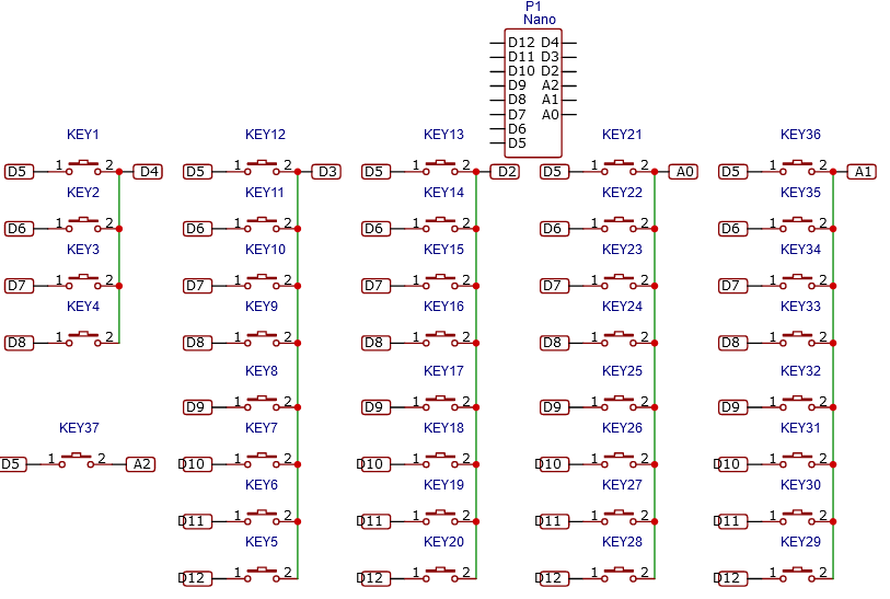
#include "HardwareSerial.h"
#define offset 48
void midi_note_off(byte channel, byte key, byte velocity);
void midi_note_on(byte channel, byte key, byte velocity);
void midi_command(byte command, byte channel, byte param1, byte param2);
byte notes_pressed[37];
void setup() {
 Serial.begin(115200);
 pinMode(12, INPUT_PULLUP);
 pinMode(11, INPUT_PULLUP);
 pinMode(10, INPUT_PULLUP);
 pinMode(9, INPUT_PULLUP);
 pinMode(8, INPUT_PULLUP);
 pinMode(7, INPUT_PULLUP);
 pinMode(6, INPUT_PULLUP);
 pinMode(5, INPUT_PULLUP);
 pinMode(4, OUTPUT);
 pinMode(3, OUTPUT);
 pinMode(2, OUTPUT);
 pinMode(A2, OUTPUT);
 pinMode(A1, OUTPUT);
 pinMode(A0, OUTPUT);
 digitalWrite(4, HIGH);
 digitalWrite(3, HIGH);
 digitalWrite(2, HIGH);
 digitalWrite(A0, HIGH);
 digitalWrite(A1, HIGH);
 digitalWrite(A2, HIGH);
}
void loop() {
 digitalWrite(4, LOW);
 for (byte j = 8; j > 4; j--)
 {
 uint8_t note = offset + (8-j);
 uint8_t key_state = digitalRead(j);

 if ( (key_state == 0) && (notes_pressed[note] == 1) )
 {
 notes_pressed[note] = 0;
 Serial.write(note + 100);
 } else if ( (key_state == 1) && (notes_pressed[note] == 0) )
 {
 notes_pressed[note] = 1;
 Serial.write(note);
 }
 }
 digitalWrite(4, HIGH);
 digitalWrite(3, LOW);
 for (byte j = 12; j > 4; j--)
 {
 uint8_t note = offset + 4 + (12 - j);
 uint8_t key_state = digitalRead(j);

 if ( (key_state == 0) && (notes_pressed[note] == 1) )
 {
 notes_pressed[note] = 0;
 Serial.write(note + 100);
 } else if ( (key_state == 1) && (notes_pressed[note] == 0) )
 {
 notes_pressed[note] = 1;
 Serial.write(note);
 }
 }
 digitalWrite(3, HIGH);
 digitalWrite(2, LOW);
 for (byte j = 12; j > 4; j--)
 {
 uint8_t note = offset + 12 + (12-j);
 uint8_t key_state = digitalRead(j);

 if ( (key_state == 0) && (notes_pressed[note] == 1) )
 {
 notes_pressed[note] = 0;
 Serial.write(note + 100);
 } else if ( (key_state == 1) && (notes_pressed[note] == 0) )
 {
 notes_pressed[note] = 1;
 Serial.write(note);
 }
 }
 digitalWrite(2, HIGH);
 digitalWrite(A0, LOW);
 for (byte j = 12; j > 4; j--)
 {
 uint8_t note = offset + 20 + (12-j);
 uint8_t key_state = digitalRead(j);

 if ( (key_state == 0) && (notes_pressed[note] == 1) )
 {
 notes_pressed[note] = 0;
 Serial.write(note + 100);
 } else if ( (key_state == 1) && (notes_pressed[note] == 0) )
 {
 notes_pressed[note] = 1;
 Serial.write(note);
 }
 }
 digitalWrite(A0, HIGH);
 digitalWrite(A1, LOW);
 for (byte j = 12; j > 4; j--)
 {
 uint8_t note = offset + 28 + (12-j);
 uint8_t key_state = digitalRead(j);

 if ( (key_state == 0) && (notes_pressed[note] == 1) )
 {
 notes_pressed[note] = 0;
 Serial.write(note + 100);
 } else if ( (key_state == 1) && (notes_pressed[note] == 0) )
 {
 notes_pressed[note] = 1;
 Serial.write(note);
 }
 }
 digitalWrite(A1, HIGH);
 digitalWrite(A2, LOW);
 for (byte j = 5; j > 4; j--)
 {
 uint8_t note = offset + 36 + (5-j);
 uint8_t key_state = digitalRead(j);
 if ( (key_state == 0) && (notes_pressed[note] == 1) )
 {
 notes_pressed[note] = 0;
 Serial.write(note + 100);
 } else if ( (key_state == 1) && (notes_pressed[note] == 0) )
 {
 notes_pressed[note] = 1;
 Serial.write(note);
 }
 }
 digitalWrite(A2, HIGH);
}
I know the last part looping over a single value is unnessecary but it should still work.
2 Answers 2
A few excerpts from the program:
#define offset 48
//...
byte notes_pressed[37]; // valid indices: 0 – 36
//...
uint8_t note = offset + (8-j); // j ≤ 8, thus note ≥ 48
//...
notes_pressed[note] = 0;
That last line writes past the end of the notes_pressed array, and
overwrites who knows what in memory. This could be the source of the
issue you are facing.
There are several issues to be considered when designing a switch matrix for an embedded processor regardless if it is a musical or computer keyboard:
- Contact bounce: This is more important for a computer keyboard then a musical keyboard. However if the switch are particularly bad, it may audible. Software may be used to mitigate the problem but will also add delay between the key press and the beginning of the note's sound.
- Pull Ups: Any logic input should not be left unconnected or floating. This can lead to unexpected results. Use Pull Up resistors (or Pull Down depending on your design) to mitigate this problem. The Arduino Uno's embedded processor (the ATmega328P) comes with built in Pull Up resistors. The Arduino IDE abstracts this feature by including a parameter it the pinMode() function call to invoke this feature.
- Rollover: In a switch matrix 1 or 2 simultaneous switch closure can be uniquely detected. However, if 3 switch closures connect 2 rows and 2 columns together, they can not be uniquely detected. This is because current can flow through the 3 closed switches activating both rows and both columns nullifying the ability for the embedded processor to scan individual rows or columns. To mitigate this problem a diode is added to all switches in the switch matrix such that there is no current path between rows or columns.
From the Rollover wikipedia page:
Most music keyboards use isolation diodes in their keyboard matrix to implement full n-key rollover, making them immune to both key ghosting and key jamming
This image if from this stack exchange question: This image is from this stack exchange question.
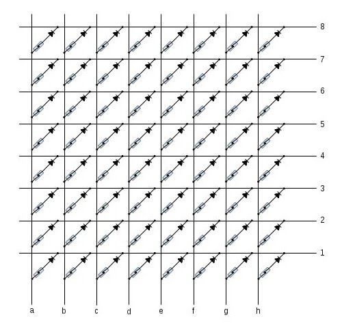
-
Thanks for your input. 1. This is something I want to mitigate later if necessary. However now I don't get any reaction to button presses or releases. 2. I am using the Arduino Pull Ups 3. The keyboard I bought has these diodes built-inmultikeys– multikeys2020年11月29日 15:36:04 +00:00Commented Nov 29, 2020 at 15:36
-
Sounds like you have already taken into account the basics. Wait ... I thought you did manage to create some notes? If you are creating no notes that means anything could be wrong including the MIDI player! Hummm ... you should start over then. Check all your wiring (using test equipment if you have any). Then use a version of your code that does not change between different columns. Then try 2 columns. Add delays in the code after changing columns to see if that helps.st2000– st20002020年11月29日 15:54:07 +00:00Commented Nov 29, 2020 at 15:54
-
Sorry I worded that wrongly. I get no reaction to button presses, whenever I uncomment more than three columns in the loop. It does not matter which ones are commented, the other ones react properly. I tried with some delays, but I will try to add these in different places, to maybe get a different behaviour.multikeys– multikeys2020年11月29日 16:00:21 +00:00Commented Nov 29, 2020 at 16:00
-
Re "built in Pull Up and Pull Down resistors": The Uno has built-in pull-ups, but no pull-downs. Re "if two switch closures occur in the same row or column, they can not be uniquely detected": It seems to me you need at least three switches to be pressed in order to create this sort of ambiguity.Edgar Bonet– Edgar Bonet2020年11月29日 16:17:21 +00:00Commented Nov 29, 2020 at 16:17
-
No pull downs? My bad - I corrected the answer. If scanning by lowering the column voltages and 2 columns are electrically connected by 2 closed switches in the same row (w/no diodes) then I do not see a way to tell the difference ... oh, I see what you mean. You don't need to tell the difference. You just need to detect they are both closed. Ok, I'll fix that too.st2000– st20002020年11月29日 18:33:39 +00:00Commented Nov 29, 2020 at 18:33
OUTPUTLOWcan pull low manyINPUT_PULLUPpins. Could you show the schematic of your keyboard + Arduino setup?forloops are messed up ......the order of keys in the columns is not all the same (if your schematic is correct) ... first column is 5 to 8 ... second column is 12 to 5 ... third column is 5 to 12 ... fourth column is 5 to 12 ... fifth column is 12 to 5 ... sixth column is a single key that does not require aforloopnote = offset + 20 + (12-j)... use increment instead ...note++