I'm working on a home automation project to control my Sommer Base+ garage door opener through Home Assistant.
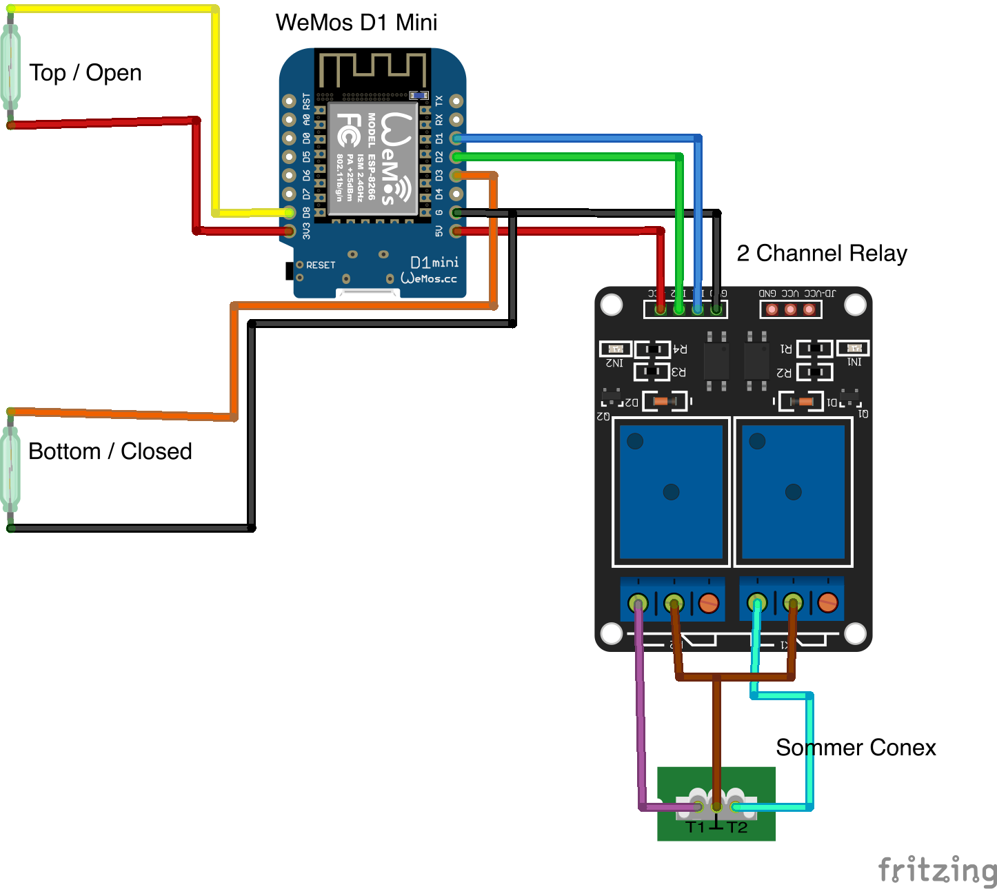
The project consists of a WeMos D1 Mini with two reed switches (to detect door open/closed) and a 5V relay to control the door opener.
When the door is open the 'top / open' switch is triggered, giving a status of open. Likewise when the door is closed, the 'bottom / closed' switch is triggered, giving a status of closed. When neither switch is triggered (i.e. when the door is in motion), the status is either opening or closing, depending on the previous status.
This works fine unless the WeMos is powered up while either reed switch is closed (so if the door is open or closed).
I know this is because D3 and D8 GPIO pins for the open/close sensors and those can put the device into boot mode (I think that's what it's called).
What I want to know is which pins are the best to use for this project.
Is it possible for me to just change to pins ?? and ?? without needing to update my code?
Is it possible that the WeMos D1 Mini isn't a good fit for what I want?
-
2GPIO 4+5 are basically the only universal inputs on the 8266; no side-effects or implementation complications.dandavis– dandavis2020年05月16日 20:12:54 +00:00Commented May 16, 2020 at 20:12
-
How are you hooking it into the Sommer? I have the same opener and would love to do this.John Spanitz– John Spanitz2020年11月24日 02:31:38 +00:00Commented Nov 24, 2020 at 2:31
-
I use a combination of the conex and output oc modules to connect to the wemos that then integrate with my Home Assistant instance.jampez77– jampez772020年11月24日 06:24:50 +00:00Commented Nov 24, 2020 at 6:24
-
Output oc: amazon.co.uk/dp/B07XZKDFX9/…jampez77– jampez772020年11月24日 06:25:06 +00:00Commented Nov 24, 2020 at 6:25
-
Conex module: amazon.co.uk/dp/B07BQYSHDV/…jampez77– jampez772020年11月24日 06:26:36 +00:00Commented Nov 24, 2020 at 6:26
1 Answer 1
NodeMCU and "Wemos D1 R2 and Mini" esp8266 (esp-12) pins and io overview
Serial
RX io3 RX0
TX io1 TX0
boot config pins with pullup or pulldown on board
D3 io0 PULLUP (LOW for boot to flashing mode)
D4 io2 TX1 PULLUP (Serial1 TX. no RX for Serial1)
D8 io15 PULLDOWN (SS pin if esp8266 is SPI slave); TX if Serial.swap()
untroubled GPIOs with optional function for I2C or SPI bus:
D1 io5 default pin for I2C SCL
D2 io4 default pin for I2C SCA
D5 io14 SPI CLK
D6 io12 SPI MISO
D7 io13 SPI MOSI; RX if Serial.swap()
RTC pin for timed deep sleep wake-up (if connected to reset pin)
D0 io16 - optional internal pulldown, internal pullup not available
not useable: on NodeMcu Sx pins io 6 to io 11 connect QIO SPI flash memory (in a very special setup the SPI bus can be used with other SPI device) (in other very special setup the QIO pins can be used as gpio)
note: most digital IO start as INPUT_PULLUP