my circuit what is supposed to be
Can someone pls help me only the two buttons clossest to the big green wire work and i don^t know why i have already tried swapping buttons
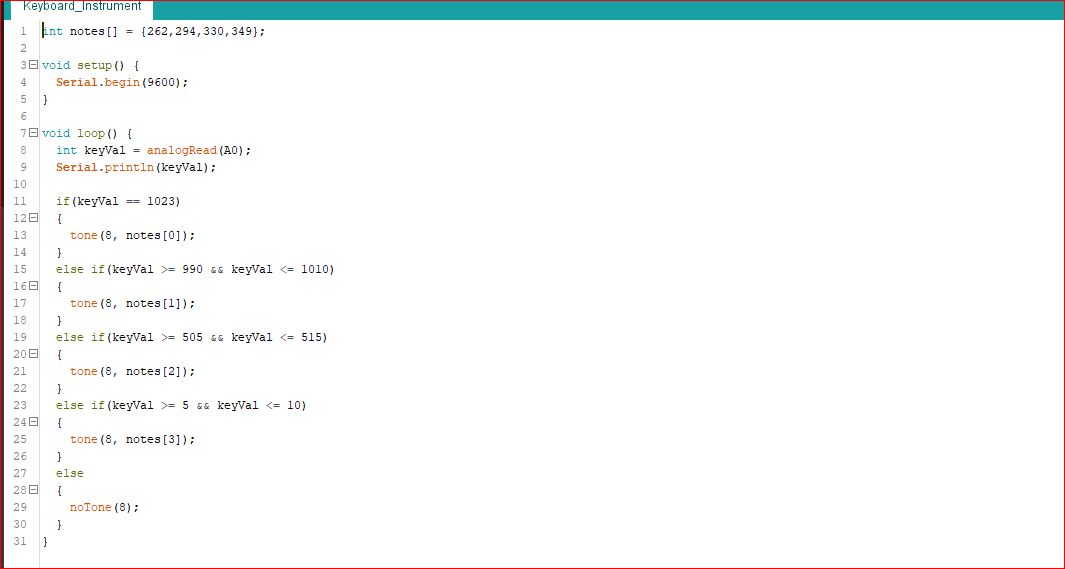
EDIT 1: my code this is my code
and i know the first two are working because they generate a tone with the piezo the third one does nothing and the last one only makes static noises
1 Answer 1
(削除) I see the problem. The connections to the first 2 buttons are correct. You're missing a yellow wire linking the output of the bottom 2 buttons to AO however, so the 3rd and 4th buttons are not connected to your A0 pin at all. Add a yellow wire between row 24 and row 20 on your breadboard. (削除ここまで)
EDIT:
I see now that there is a green wire connecting rows 24 and 20 together. However, that is the likely place where things go wrong. I would suggest taking a couple of jumpers and connecting them to a multimeter set to continuity mode. Put one in row 28, and then test continuity to row 24, row 20, and row 16.
One of your wires may not be seated into the breadboard properly, or you may even have a bad row on your breadboard. I've seen that before.
EDIT #2:
A multimeter is your friend. If you don't have one, you should get one, and learn how to use it. It's invaluable for troubleshooting circuits. (Get one that has a continuity mode that beeps when it detects continuity, and that has auto-ranging voltage and resistance measurements.)
-
thank you this really helped me think what if it is the breadboard so i took of the sticky backside and there were some loose pieces of metal i pushed on these pieces and now it worksChiel Bouwman– Chiel Bouwman2019年04月16日 12:08:55 +00:00Commented Apr 16, 2019 at 12:08
-
only problem i have now is that the analog read value from the when i press the last button isn't a steady 1023 but even if i connect the analog directly to the 5v line it isn't steady so i think that should be solved in code but i am not sureChiel Bouwman– Chiel Bouwman2019年04月16日 12:17:36 +00:00Commented Apr 16, 2019 at 12:17
-
Yes, I would suggest not matching a specific value. Write your code to check for a range of analog values. Your circuit is a voltage divider, and the button with no resistor (the bottom one in your illustration) will give a value close to, but not quite, 5V. I'd suggest looking for a value ≥1020 for that button. Check the value you get for the other buttons and implement ranges with upper/lower bounds for those.Duncan C– Duncan C2019年04月16日 15:08:02 +00:00Commented Apr 16, 2019 at 15:08
-
thanks alot for the reply the value >= 1020 made it work perfectly for me. Again thanks for your helpChiel Bouwman– Chiel Bouwman2019年04月16日 15:17:10 +00:00Commented Apr 16, 2019 at 15:17
{}button to format itserial.print()command .... please open the serial monitor in the arduino IDE and find out what values are being printed for each button press .... add those values to your question above