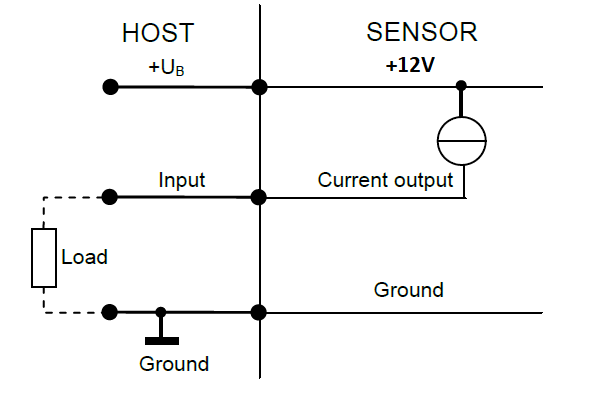
I've got a 3 wire 4-20mA current output sensor, externally powered by 12V, which I want to read from an Arduino Uno (5V). The sensor connection diagram is below, but I don't understand why it says to connect the sensor power out (12V) to the host as well?
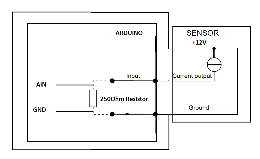
Below that is how I think I should connect it (i.e. with the power out from the sensor simply connected back to itself). Will this work? Could I damage my board or, far worse, the sensor itself this way?
Thanks alot!
-
If the sensor outputs 12V I wouldn't advice connecting it directly to an Arduino GPIO.Michel Keijzers– Michel Keijzers02/14/2018 20:09:30Commented Feb 14, 2018 at 20:09
-
where did the diagram come from? Try it with a DMM and see what your ranges aredandavis– dandavis02/14/2018 20:12:41Commented Feb 14, 2018 at 20:12
-
@dandavis Hi, try what with a DMM? The voltage across +UB and ground on the sensor? The diagram came from the datasheet for the sensorOliver Walters– Oliver Walters02/14/2018 20:19:54Commented Feb 14, 2018 at 20:19
-
@MichelKeijzers Hi, I know. I thought 3 wire sensors you can simply connect a 250Ohm shunt resistor to the current output, and measure the voltage drop across that, which should then only be 0-5V. But I don't understand why the diagram says connect the power supply to the host as well?Oliver Walters– Oliver Walters02/14/2018 20:22:11Commented Feb 14, 2018 at 20:22
-
Digital Multi Meter; you can use it to tell if your setup works w/o frying your unodandavis– dandavis02/14/2018 20:50:00Commented Feb 14, 2018 at 20:50
1 Answer 1
The connection diagram is showing the sensor being powered by a host that runs at 12v. Normally the host would provide the power. However, you provide the power yourself from another source. So you don't need power from the host, so you do not connect the 12v to the host.
All you need is the signal and the ground (along with a load resistance to convert the current into a voltage, and maybe some over voltage protection on the signal in case the load resistance becomes disconnected or fails in some other way).
schematic
simulate this circuit – Schematic created using CircuitLab
In that example RL is the "Load" resistor and is calculated as the nearest common resistance value that gives, with 20mA (assuming a standard 4-20mA sensor) through it, close to 5V across it without going over. In this case, 4.4V, which is good. RP is a "protection" resistor to prevent damage to the sensor should the load resistor fail, which would give 12V (though limited in current) across the zener diode D1. It just limits the current that can flow through D1 and be pulled by an effective short circuit across the sensor's output when D1 fails over (if it ever does). D1 is there to prevent the ADC from ever seeing any more than 5.1V in the event of a problem.
Explore related questions
See similar questions with these tags.