I uploaded the Blink sketch (from the ESP8266 examples, in the Arduino IDE) successfully.
Depending on which wire configuration I am using two different things happen:
wiring 1:
CH_PD -> 3.3V
VCC -> 3.3V
RST -> GND
GPI02 -> LED
GND -> GND
wiring 2:
VCC -> 3.3V
RST -> GND
GPI02 -> LED
GND -> GND
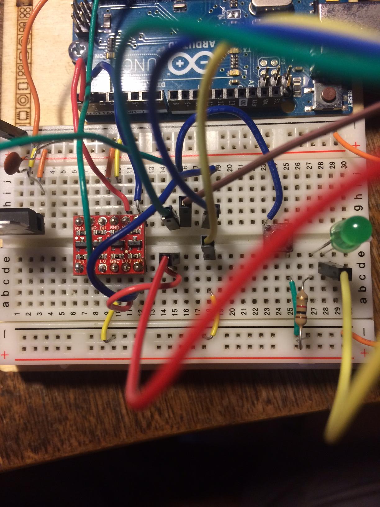
There are TX/RX lines in the picture from when I was flashing - they aren't being used for running the sketch.
With wiring 1 the LED stays on (doesn't blink) - I was wondering if this was because I still had the VCC -> 3.3V connected. So I disconnected that, which gives way to wiring 2.
With wiring 2 the LED doesn't come on at all, it is the same as wiring 1 except without VCC -> 3.3V.
Why is it constant when 3.3V is going to VCC, and constantly off when I disconnect it? Why doesn't it blink using wiring 2?
UPDATE
A diagram as requested, sorry it was my first time doing this:
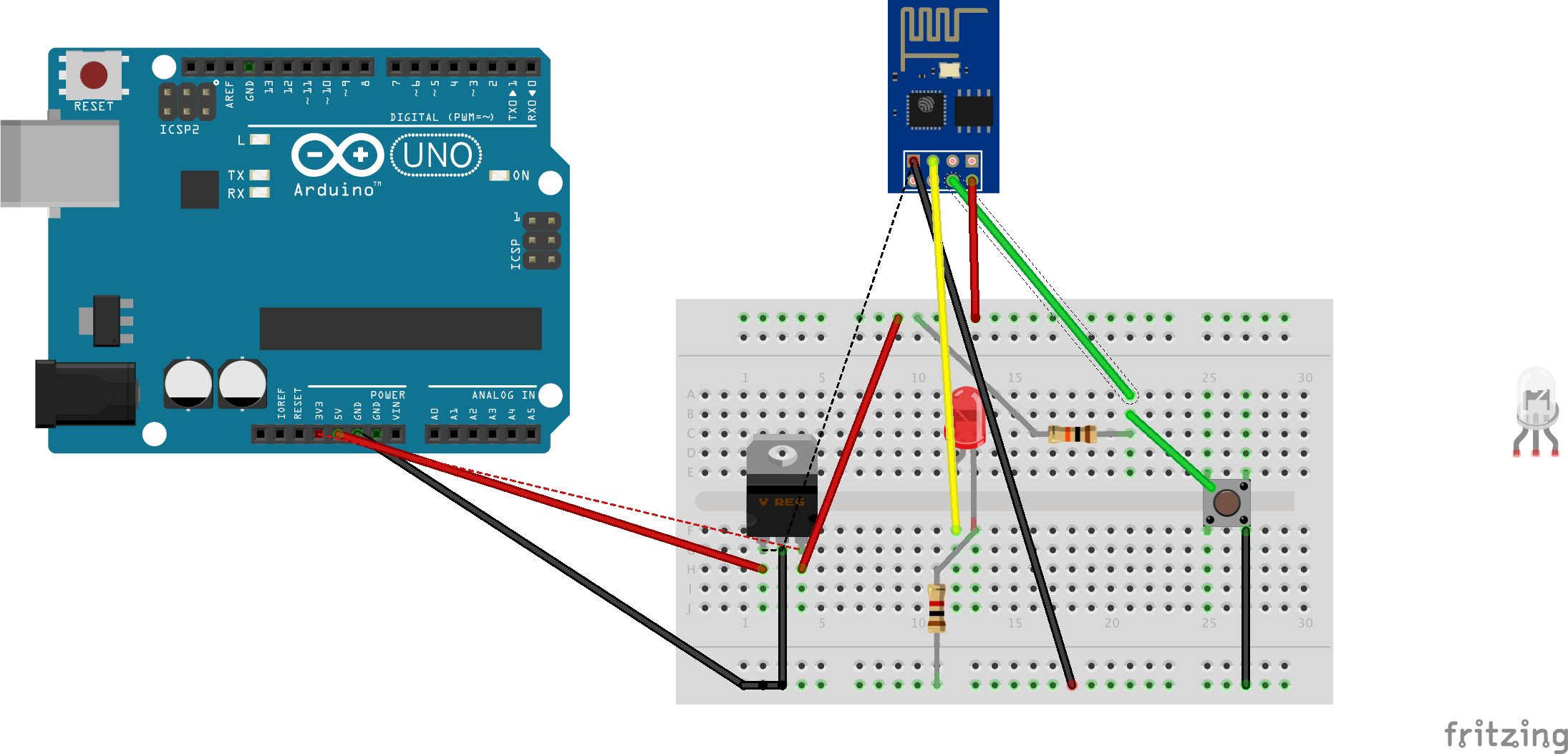
Code:
/*
 ESP8266 Blink by Simon Peter
 Blink the blue LED on the ESP-01 module
 This example code is in the public domain
 The blue LED on the ESP-01 module is connected to GPIO1
 (which is also the TXD pin; so we cannot use Serial.print() at the same time)
 Note that this sketch uses LED_BUILTIN to find the pin with the internal LED
*/
void setup() {
 pinMode(LED_BUILTIN, OUTPUT); // Initialize the LED_BUILTIN pin as an output
}
// the loop function runs over and over again forever
void loop() {
 digitalWrite(LED_BUILTIN, LOW); // Turn the LED on (Note that LOW is the voltage level
 // but actually the LED is on; this is because
 // it is acive low on the ESP-01)
 delay(1000); // Wait for a second
 digitalWrite(LED_BUILTIN, HIGH); // Turn the LED off by making the voltage HIGH
 delay(2000); // Wait for two seconds (to demonstrate the active low LED)
}
-
1The picture shows an Arduino Uno, and no ESP8266 -- where is your ESP8266?jose can u c– jose can u c2017年09月19日 18:20:05 +00:00Commented Sep 19, 2017 at 18:20
-
its out of the picture - the wires that blur off the screen lead to it...i was trying to show wiring on board - all that is going on with it is the power light is on as it should be.ewizard– ewizard2017年09月19日 18:42:02 +00:00Commented Sep 19, 2017 at 18:42
-
with a ESP-01S, all you'd need is GND+VCC+GPIO2...dandavis– dandavis2017年09月19日 19:43:22 +00:00Commented Sep 19, 2017 at 19:43
-
yah it the extra wires are from flashing...would what im doing now not work for some reason? I disconnected the GPIO0 from ground and disconnected 3.3v from CH_PD...didnt bother with serial linesewizard– ewizard2017年09月19日 20:13:50 +00:00Commented Sep 19, 2017 at 20:13
2 Answers 2
You should connect Vcc to 3.3V, because that's how the ESP8266 is powered. RST is active-low reset and should be pulled to 3.3V
-
I am sending to LV...its the green wire, it gets blocked out. So running standalone vcc should be 3.3v? what about ch_pd? Oh wait I messed up my pins...wiring 2 vcc is still connectedewizard– ewizard2017年09月19日 19:00:14 +00:00Commented Sep 19, 2017 at 19:00
-
Just saw you have RST to GND, RST is active-low reset, so it needs to be pulled high to 3.3V otherwise the device is always in reset.jose can u c– jose can u c2017年09月19日 19:01:45 +00:00Commented Sep 19, 2017 at 19:01
-
oh wow that could be it ill try...im new to this...to pull high where would i put the resistor? the leg on the switch across from the blue wire? (vertical)ewizard– ewizard2017年09月19日 19:04:01 +00:00Commented Sep 19, 2017 at 19:04
-
You just put a resistor between RST and 3.3V directly. Instead of RST to GND, you RST to one side of resistor, then plug the other side of the resistor to 3.3V.jose can u c– jose can u c2017年09月19日 19:07:46 +00:00Commented Sep 19, 2017 at 19:07
-
would i move my reset button to in between RST and resistor->3.3v. to switch it on and off that power?ewizard– ewizard2017年09月19日 19:28:59 +00:00Commented Sep 19, 2017 at 19:28
I can't comment as my karma is too low so if I am wrong please just someone let me know and I'll simply delete.
I thought that the RST pin being pulled to ground resets the chip, if this is the case surely in your setup you are constantly reseting your chip, so it won't do anything. My understanding is that you should have the reset pin pulled up to 3.3V with a 10K resistor.
-
thanks...where does the resistor go? this is my first time "pulling"...im guessing the leg on the bottom left to 3.3v?ewizard– ewizard2017年09月19日 19:05:52 +00:00Commented Sep 19, 2017 at 19:05
-
I'm not sure if it's the leg on the bottom left... You havnt provided a picture of your esp8266 board. But it should connect your esp8266 RST pin to the 3.3V source!C.W.G– C.W.G2017年09月19日 19:08:17 +00:00Commented Sep 19, 2017 at 19:08
-
instead of ground? so my switch could be in between RST and 3.3v?ewizard– ewizard2017年09月19日 19:27:43 +00:00Commented Sep 19, 2017 at 19:27
-
Yes, exactly. Like what Jose saysC.W.G– C.W.G2017年09月19日 19:28:46 +00:00Commented Sep 19, 2017 at 19:28
-
I reflashed the code and no luck...see comment on below answerewizard– ewizard2017年09月19日 20:06:34 +00:00Commented Sep 19, 2017 at 20:06
Explore related questions
See similar questions with these tags.