I am trying to connect to esp8266 using Arduino UNO. There are various things on the internet having mixed information and hence I am seeking some clarity.
I followed these instructions, but could not get to connect to ESP8266 using AT command. http://cordobo.com/2300-flash-esp8266-01-with-arduino-uno/
I have following questions:
- Can I connect ESP8266 directly to Tx/Rx without voltage divider or level shifter? I also suspect that the voltage divider connections are wrong. As per my understanding, the Tx from Arduino should be divided, and the divider output should be connected to ESP8266.
- When I connected the shield as described, the shield gets hot. Is there any way to conclude if the shield is damaged or not?
- When I connect the device using voltage divider the blue LED on the shield also lights up. Without divider, it does not light up. What is the significance of the blue LED?
Hardware
ESP8266-01 pinout
Circuit using voltage divider
Circuit without voltage divider
-
Which connection method did you use? There are several in the page you referenced. Better, post your schematic.user31481– user314812017年08月10日 09:15:13 +00:00Commented Aug 10, 2017 at 9:15
-
I tried both the methods. The one without voltage divider (section 3.2) and the one with voltage divider (Section 3.1). I could not get the AT commands work with either method. When I connect using voltage divider the blue LED was turned on. When connecting without voltage divider the blue LED did not light.Manish Sapariya– Manish Sapariya2017年08月10日 09:32:27 +00:00Commented Aug 10, 2017 at 9:32
3 Answers 3
There are a number of issues with the tutorial you've listed there.
Firstly, a voltage divider is very highly recommended as the ESP8266 cannot handle more than 3.3V, however, the connections for the voltage divider in the tutorial you linked to are the wrong way round (as you suspected).
Secondly, you cannot power the ESP8266 directly from the Arduino, as the power requirements are higher than the Arduino's on board 3.3V regulator. A separate power supply or regulator is recommended. This might be cause of it getting hot (the onboard regulator maybe - but I can't be sure as there is not enough information from your initial post as to exactly what is getting hot).
There are 2 LED's on the ESP8266 shield (the one used in the tutorial you've linked to) one is power and the blue one is wifi communication.
The other potential issue with the tutorial you've linked to is that they have used Arduino pins 0 and 1 to connect to the ESP8266 - while this will work, the problem is that the Arduino uses pins 0 and 1 to communicate over USB with a computer, which means that in in that configuration you cannot use Serial monitor to send/receive data.
-
Thanks for the confirmation about the voltage divider. I did try with Arduino 3.3V output and surprisingly it was shiled that was getting hot and not Arduino.Manish Sapariya– Manish Sapariya2017年08月11日 03:19:46 +00:00Commented Aug 11, 2017 at 3:19
-
If you don't use Arduino 0 and 1 then you can use SoftwareSerial, but that can not support high data rates. 9600 is usually OK, I don't know about higher.Code Gorilla– Code Gorilla2017年08月11日 12:01:03 +00:00Commented Aug 11, 2017 at 12:01
-
Arduino Tx — resistor (1/3) — tap to ESP-01 Rx — resistor (2/3) – GNDMatsK– MatsK2017年08月11日 13:02:57 +00:00Commented Aug 11, 2017 at 13:02
-
@holmez Do I need to do same for Rx pin well?Manish Sapariya– Manish Sapariya2017年08月14日 03:51:45 +00:00Commented Aug 14, 2017 at 3:51
-
@ManishSapariya You only need to do it for the Arduino Tx, because you're changing the transmission voltage from 5V to 3.3V. The ESP8266 will transmit at 3.3V, which the Arduino is happy with.Holmez– Holmez2017年08月14日 08:23:02 +00:00Commented Aug 14, 2017 at 8:23
I'm working with ESP-12S which use ESP8266 recently.
My main goal is to use UART-WIFI passthrough mode, so I only need VCC, RX, TX, GND.
These are the steps I take:
- Use USB to TTL converter to link WIFI module to PC for WIFI configuration. (two USB converter were used for power issue)
On PC I used minicom to open the USB serial. Use AT commands(espressif.com/sites/default/files/documentation/4a-esp8266_at_instruction_set_en.pdf) to config WIFI module:
AT+RESTORE // restores the factory default settings
AT+GMR // checks version information
AT+RST // restarts the module
AT+CWMODE_DEF=1 // set station mode
AT+CWJAP_DEF="APname","password" // connect to AP
AT+CWDHCP_DEF=1,1 // set station mode with DHCP
AT+CWAUTOCONN=1 // auto connect
AT+CIFSR // show local IP
AT+PING="10.0.1.1" // ping network gate
AT+CIPSTART="TCP","10.0.1.116",2048 // setup TCP to server
AT+CIPMODE=1 // set UART-WIFI passthrough mode
AT+CIPSEND // enter UART-WIFI passthrough mode
AT+SAVETRANSLINK=1,"10.0.1.116",2048,"TCP" // save configuration in WIFI module
After configuration, hook WIFI module to Arduino (actully I'm using stm32, but it's the same) UART pins. When power on, the WIFI module will automatically connet to AP and setup TCP link to server and enter UART-WIFI passthrough mode.
- If you want to exit UART-WIFI passthrough mode, send '+++' on UART end, without '\r\n' and '+++' must be sent continuously (type '+++' in minicom won't work).
as for your questions,
Voltage divider is used, but pay attention to RXD TXD link problem. (RXD to TXD, TXD to RXD)
My WIFI module also gets hot, but working properly.
I don't know the blue LED's function, but I did remember reading about it some where, maybe in the documentation.
Some ESP boards are 5v tolerant on the digital pins, some aren't. So it depends on what board you have, I don't think the one in the tutorial is.
If you are using serial to communicate the a resistor divider will not work. You need a proper level shifter, which you should be able to get for less than a 1ドル. Remember you will probably need to down shift the Tx from the Arduino and Up Shift the RX to the Arduino.
-
1A resistor divider will work as long as the resistors are low enough, but not too low, resistance. I found 1K + 2K worked, but 10K + 20K didn't.Majenko– Majenko2017年08月10日 14:33:03 +00:00Commented Aug 10, 2017 at 14:33
-
1what do you mean by "some are, some aren't" 5v tolerant? Which ones are which? where did you find such information?dandavis– dandavis2017年08月10日 19:45:57 +00:00Commented Aug 10, 2017 at 19:45
-
@dandavis - The ESP8266 chip data sheet says that the GPIO pins only accept 3.3v max (download.arduino.org/products/UNOWIFI/…), but I know the Node Lua and Wemos D1 are 5v tolerant (well they didn't burn). I don't have a definitive list, in fact I would even stake a donut on the fact that all Wemos D1s are 5v tolerant, because there are so many different designs of the "same thing"Code Gorilla– Code Gorilla2017年08月11日 07:30:18 +00:00Commented Aug 11, 2017 at 7:30
-
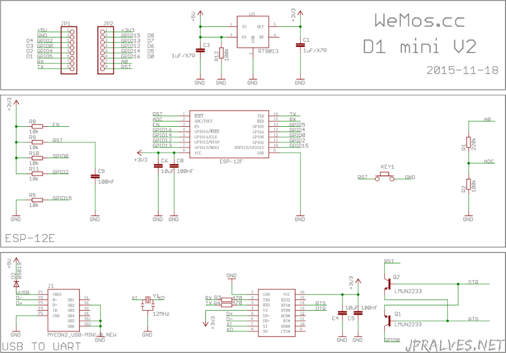
1looking at the D1's schematic, the GPIOs are almost all wired straight-through to the 12F module, which would imply all 12Fs share the property. I believe it comes down to quality/die luck: the only one (of dozens) i've had that was noticeably finicky w/ 5v components was one that also froze when "overclocked" to 160. The main issues likely stem from too much heat, and a D1 probably dissipates heat better than an ESP01, commanding more volume in an enclosure if nothing else...dandavis– dandavis2017年08月11日 09:30:07 +00:00Commented Aug 11, 2017 at 9:30
-
I agree, I suspect they should all be 3.3, but sometimes you get away with it :)Code Gorilla– Code Gorilla2017年08月11日 11:59:12 +00:00Commented Aug 11, 2017 at 11:59