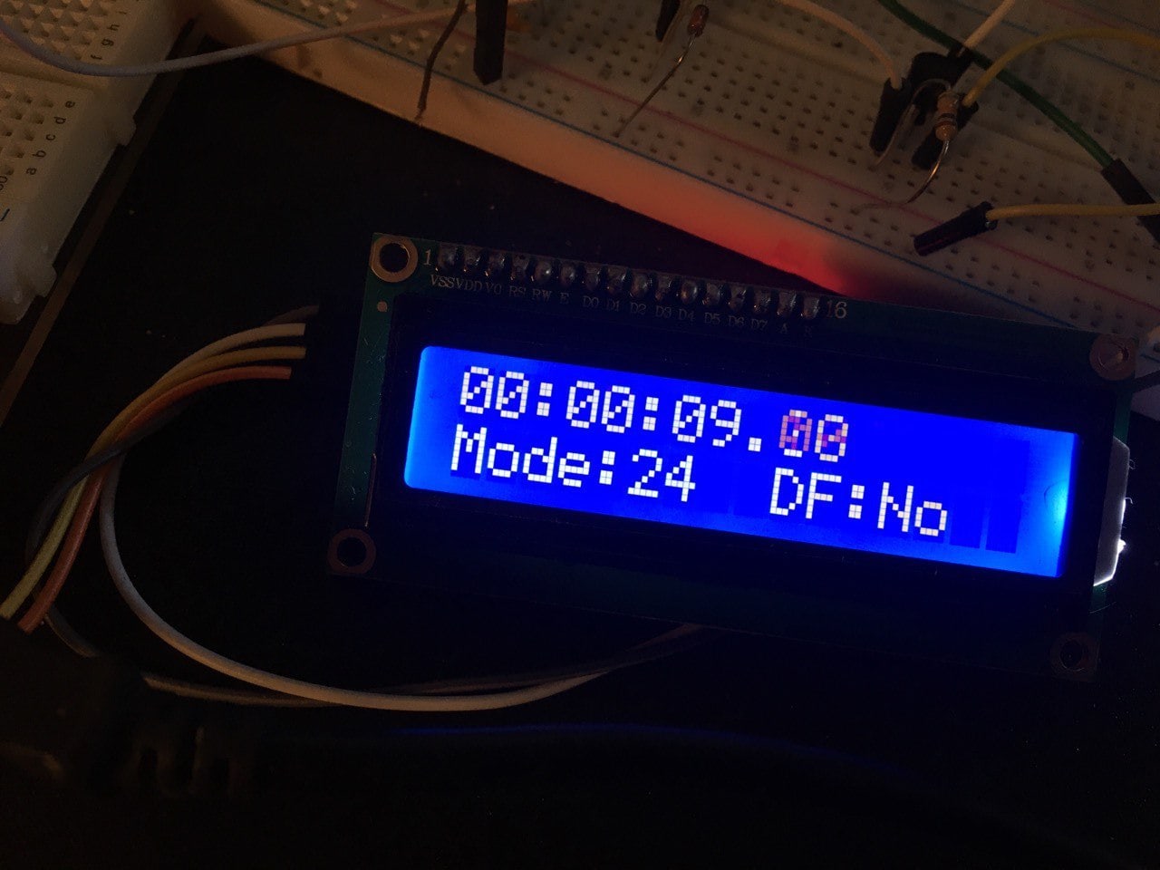
I've managed to adapt some code from the Arduino forums to display timecode on an LCD display.
What I would like some extra help with is first is there a way of defining the one_time_max etc differently depending on the high low state of a pin? This way I could use a switch to change the times so it could switch between NTSC and PAL.
Secondly would anyone be kind enough to explain what is happening in the middle part of this code? I've made some notes but any help would be really appreciated.
Here is a picture of how it's going so far. I'll keep you guys up to date as the project continues :)
[![enter image description here][1]][1]
 // Code from forum post Dec 12, 2007

 // include the library code:
 #include <LiquidCrystal.h>

 // initialize the library with the numbers of the interface pins
 LiquidCrystal lcd(12, 11, 5, 4, 3, 2);
 #define one_time_max 600 // these values are setup for PA video
 #define one_time_min 400
 // It's the durstion of a one and zero with a little bit of room for error.
 #define zero_time_max 1050 //
 #define zero_time_min 950 //


 #define icpPin 8 // ICP input pin on arduino
 //#define one_time_max 475 // these values are setup for NTSC video
 //#define one_time_min 300 // PAL would be around 1000 for 0 and 500 for 1
 //#define zero_time_max 875 // 80bits times 29.97 frames per sec
 //#define zero_time_min 700 // equals 833 (divide by 8 clock pulses)

 #define end_data_position 63
 #define end_sync_position 77
 #define end_smpte_position 80

 volatile unsigned int pin = 13;
 volatile unsigned int bit_time;
 // volatile instructs the variable to be stored in RAM
 volatile boolean valid_tc_word;
 // boolean can be either of two values true or false but default to false
 volatile boolean ones_bit_count;
 // boolean can be either of two values true or false but default to false
 volatile boolean tc_sync;
 // boolean can be either of two values true or false but default to false
 volatile boolean write_tc_out;
 // boolean can be either of two values true or false but default to false
 volatile boolean drop_frame_flag;
 // boolean can be either of two values true or false but default to false
 volatile byte total_bits; //this stores a an 8-bit unsigned number
 volatile byte current_bit; //this stores a an 8-bit unsigned number
 volatile byte sync_count; //this stores a an 8-bit unsigned number

 volatile byte tc[8]; //this stores a an 8-bit unsigned number
 volatile char timeCode[11]; //this stores a an 8-bit unsigned number

 /* ICR interrupt vector */
 ISR(TIMER1_CAPT_vect) {
 //ISR=Interrupt Service Routine, and timer1 capture event
 //toggleCaptureEdge
 TCCR1B ^= _BV(ICES1);
 //toggles the edge that triggers the handler so that the duration of both high and low pulses is measured.
 bit_time = ICR1; //this is the value the timer generates
 //resetTimer1
 TCNT1 = 0;
 // Ignore phase changes < time for 1 bit or > time for zero bit (zero bit phase change time is double that of 1 bit)
 if ((bit_time < one_time_min) || (bit_time > zero_time_max)) {
 // this gets rid of anything that's not what we're looking for
 total_bits = 0;
 } else {
 // If the bit we are reading is a 1 then ignore the first phase change
 if (ones_bit_count == true)
 // only count the second ones pulse
 ones_bit_count = false;
 else {
 // We have already checked the outer times for 1 and zero bits so no see if the inner time is > zero min
 if (bit_time > zero_time_min) {
 // We have a zero bit
 current_bit = 0;
 sync_count = 0; // Not a 1 bit so cannot be part of the 12 bit sync
 } else {
 // It must be a 1 bit then
 ones_bit_count = true; // Flag so we don't read the next edge of a 1 bit
 current_bit = 1;
 sync_count++; // Increment sync bit count
 if (sync_count == 12) {
 // part of the last two bytes of a timecode word
 // We have 12 1's in a row that can only be part of the sync
 sync_count = 0;
 tc_sync = true;
 total_bits = end_sync_position;
 }
 }

 if (total_bits <= end_data_position) {
 // timecode runs least to most so we need
 // to shift things around
 tc[0] = tc[0] >> 1;
 for(int n=1;n<8;n++) {
 //creates tc[1-8]
 if(tc[n] & 1) tc[n-1] |= 0x80;
 tc[n] = tc[n] >> 1;
 }
 if(current_bit == 1) tc[7] |= 0x80;
 }
 total_bits++;
 }
 if (total_bits == end_smpte_position) {
 // we have the 80th bit
 total_bits = 0;
 if (tc_sync) {
 tc_sync = false;
 valid_tc_word = true;
 }
 }
 if (total_bits <= end_data_position) {
 // timecode runs least to most so we need
 // to shift things around
 tc[0] = tc[0] >> 1;
 for(int n=1;n<8;n++) {
 //creates tc[1-8]
 if(tc[n] & 1) tc[n-1] |= 0x80;
 tc[n] = tc[n] >> 1;
 }
 if(current_bit == 1) tc[7] |= 0x80;
 }
 total_bits++;
 }

 if (total_bits == end_smpte_position) {
 // we have the 80th bit
 total_bits = 0;
 if (tc_sync) {
 tc_sync = false;
 valid_tc_word = true;
 }
 }

 if (valid_tc_word) {
 valid_tc_word = false;
 timeCode[10] = (tc[0]&0x0F)+0x30;
 // frames this converst from binary to decimal giving us the last digit
 timeCode[9] = (tc[1]&0x03)+0x30;
 // 10's of frames this converst from binary to decimal giving us the first digit
 timeCode[8] = ':';
 timeCode[7] = (tc[2]&0x0F)+0x30; // seconds
 timeCode[6] = (tc[3]&0x07)+0x30; // 10's of seconds
 timeCode[5] = ':';
 timeCode[4] = (tc[4]&0x0F)+0x30; // minutes
 timeCode[3] = (tc[5]&0x07)+0x30; // 10's of minutes
 timeCode[2] = ':';
 timeCode[1] = (tc[6]&0x0F)+0x30; // hours
 timeCode[0] = (tc[7]&0x03)+0x30; // 10's of hours
 drop_frame_flag = bit_is_set(tc[1], 2);
 //detects whether theree is the drop frame bit.
 write_tc_out = true;
 }
 }

 void setup() {
 lcd.begin (16, 2);
 pinMode(icpPin, INPUT); // ICP pin (digital pin 8 on arduino) as input
 bit_time = 0;
 valid_tc_word = false;
 ones_bit_count = false;
 tc_sync = false;
 write_tc_out = false;
 drop_frame_flag = false;
 total_bits = 0;
 current_bit = 0;
 sync_count = 0;
 lcd.print("FINISHED SETUP");
 delay (1000);
 TCCR1A = B00000000; // clear all
 TCCR1B = B11000010; // ICNC1 noise reduction + ICES1 start on rising edge + CS11 divide by 8
 TCCR1C = B00000000; // clear all
 TIMSK1 = B00100000; // ICIE1 enable the icp
 TCNT1 = 0; // clear timer1
 }

 void loop() {
 if (write_tc_out) {
 write_tc_out = false;
 if (drop_frame_flag)
 lcd.print("TC-[df] ");
 else
 lcd.print("TC-NO DROP FRAME");
 lcd.setCursor(0, 1);
 lcd.print((char*)timeCode);
 lcd.print("\r");
 lcd.setCursor(11, 1);
 lcd.print("......");
 delay (30);
 lcd.clear();
 }
 }
111
 [1]: https://i.sstatic.net/V6CxE.jpg
-
So if a pin were to be high or low, what variables would you change? And what would you change them to?hichris123– hichris1232014年02月22日 16:32:52 +00:00Commented Feb 22, 2014 at 16:32
-
Hiya, the values i'd want to change are the one_time_min etc. And I want to change them to the values required to decode NTSC rather than PALuser3316519– user33165192014年02月22日 16:55:23 +00:00Commented Feb 22, 2014 at 16:55
-
I wonder how the circuit configuration. I would appreciate a more informed picture or drawing. {email address removed by moderator}user4791– user47912014年11月13日 09:04:48 +00:00Commented Nov 13, 2014 at 9:04
3 Answers 3
The one_time_max, one_time_min, zero_time_max and zero_time_min are all defines at the top of the file. This will insert them as constant values at compile time. This makes changing the code to deal with them slightly awkward, but not impossible.
Oddly, the one_time_max value isn't used, but the others are. To allow you to switch between PAL and NTSC, I would do the following (this is marginally lazy, but quick):
- change one_time_max to ONE_TIME_MAX_NTSC and ONE_TIME_MAX_PAL so that you have two defined constants for each part. Caps is convention for defines.
- create a new global variable, a boolean, that is a flag to decide if PAL or NTSC is to be decoded.
- every time that one of the constant is used, use a conditional statement based on the global variable to decided which constants are used.
- use the input from a button to decided the value of the global variable.
-
Thank you! i'll give this a go and see what happens. I don't suppose you could explain how adding the 0x0F+0x30 converts it from presumably a hex value to a decimal?user3316519– user33165192014年02月22日 16:57:36 +00:00Commented Feb 22, 2014 at 16:57
-
The &ing seems superfluous in this situation. 0x30 is ASCII for 0, so if you represent 0 as 0x00 and 9 as 0x9, then adding 0x30 converts to ASCII.Cybergibbons– Cybergibbons2014年02月22日 22:02:36 +00:00Commented Feb 22, 2014 at 22:02
I am in the process of implementing exactly the same thing. The simplest way around this problem is simply to do away with the one_time_max and one_time_min variables and simply implement a mid_point value, testing the bit_time against this for one and zero values. By simply testing for a mid_point value, it allows the routine to tune itself for integer/non-integer timecode values from 24fps thorough to 30fps.
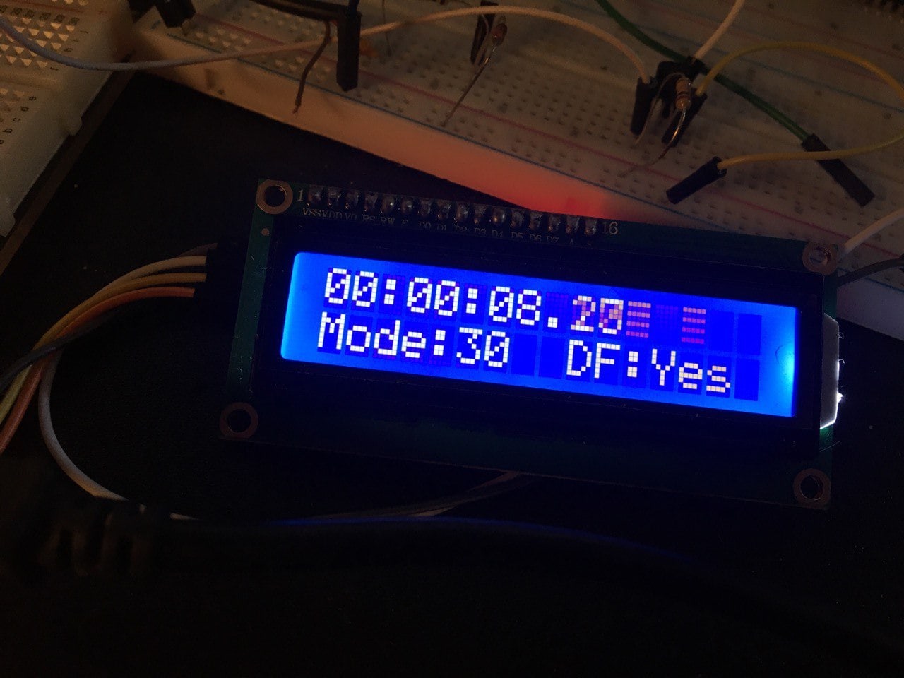
I am implementing a similar project, but my timecode reader is built into the clapperboard itself.
https://improduction.ru/tags/imslate-1/
The thing is that the bit length depends on the FPS. I just "listened" to the signal from my Zoom F8 recorder and then started the reference data. While receiving data from the cable, I simply compare them and determine the frequency. That's all.
https://improduction.ru/all/elektronnaya-hlopushka-imslate-1-pro-chtenie-taymkoda/
-
I see that you have a similar project. You have nice images. I have no idea how this attempts to address the question though.timemage– timemage2021年01月24日 13:20:17 +00:00Commented Jan 24, 2021 at 13:20
-
I wrote how I solved this problem in general terms and showed what my display looks like. I determine frequencies and DF / NF in real time. But, I will not show the codeEndyVelvet– EndyVelvet2021年01月26日 13:24:53 +00:00Commented Jan 26, 2021 at 13:24