I am working on a project for knowing the position of a DC motor which has a hall sensor built into it. I am a newbie into programming using the Arduino Uno R3. After some forum search and self checks, I cannot pass this hurdle. I hope I can frame the questions properly here.
My Problem: The DC motor hall sensor sends out 2 high pulse of 11.3V - 13V with a duration of 2.8ms for each revolution. My Arduino interrupt pin doesn't read the high pulse as it gives me "0" count after motor spin (I run 50 loops and results remain the same).
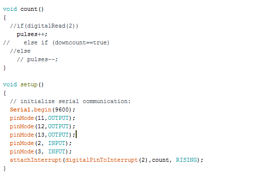
Interupt pin asssigment with function call
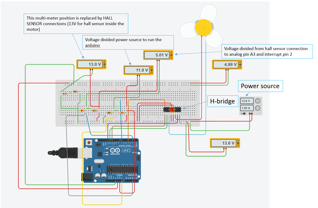
On my breadboard, I use a voltage divider to reduce hall-effect ouput from max 13V to 5V so that the Arduino pin 2 can read rising voltage when it jumps to 5V (low should be 2.5V).
Couple of things I noted during the motor spin -
a) The millis() function returns 79-81ms per sketch run
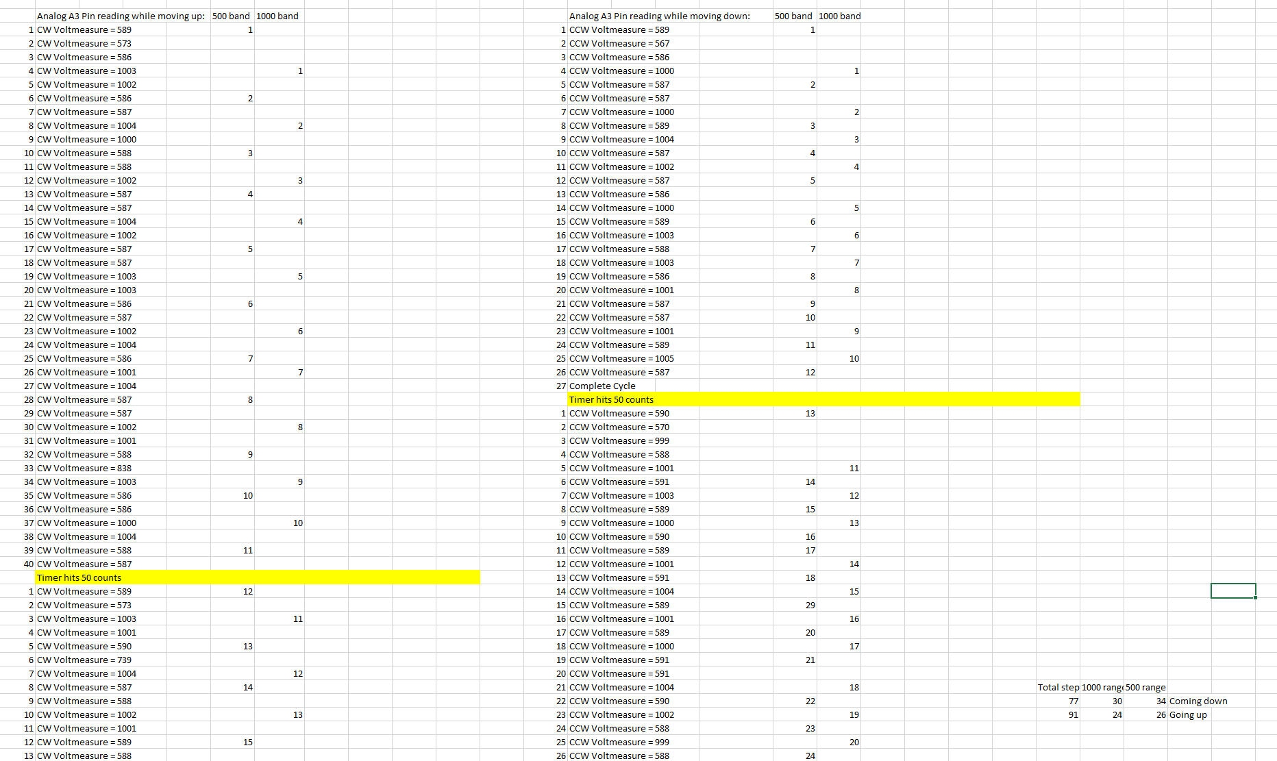
b) The same hall sensor output if connected to analog pin reads 580,590,590,1001, 1012, 580, 580.. etc. I cannot gauge position of the motor by using these values as they are inconsistent on the way up Vs. way down.
I have attached analog readings while going up and down in snap shot below: enter image description here 2 questions I have:
- Why is the pin 2 not detecting a high pulse? will it not be able to read 2.8ms durations because of motor speed (9.5 rev/s or 570rpm)?
- Is it possible to gauge anything from Analog read function? Am I missing something?
Thanks in advance for all responses.. Any questions regarding the circuit, I will be more than happy to post them.
5 Answers 5
First, better to see whole source and schematics.
"Why is the pin 2 not detecting"
Check: 1. Hall sensor connected to Pin 2
pulses variable declared as volatile.
Check if internal pull up resistor setup consistent with hall sensor connection.
Check that Hall sensor's lowest signal voltage is below 0.3 VCC (you said 5V, so it should drop below 1.5V), BTW 580 - the lowest analog value you showed means 2.83V
Check you are not using nointerrupt();
"Is it possible to gauge anything from Analog read function? Am "
Yes. Analog read takes about 0.1 ms in default setup, so should make at least 1000 reads per second to catch peak.
So, Easiest way is to choose some value like 600, when analog read is above mark it as Rising when it drops below mark is Falling. More complicated ways will include some training and hysteresis to improve detection.
Also I suggest to use voltage limiter instead of voltage divider. This gives better detection.
-
1,2, 5 is checked. I will check the rest.anuzarduino– anuzarduino2016年11月24日 14:23:58 +00:00Commented Nov 24, 2016 at 14:23
-
Best way is to test where the problem is to replace Hall sensor with button.Andrey Visochan– Andrey Visochan2016年11月25日 10:08:57 +00:00Commented Nov 25, 2016 at 10:08
-
if with button arduino don't increase pulses variable, then problem is inside arduino (sketch code, port setup or internal schema) otherwise it is outside. Anyway, I agreed with both Nicks, it will be helpful to provide whole sketch code.Andrey Visochan– Andrey Visochan2016年11月25日 10:13:58 +00:00Commented Nov 25, 2016 at 10:13
-
@ all: Lab is closed for thanksgiving. Will surely respond on the code and other items by Mondayanuzarduino– anuzarduino2016年11月26日 18:04:33 +00:00Commented Nov 26, 2016 at 18:04
All,
Here is the code:
int flag = 1;
int speedo = 255;
 int counter =0; //counts the number of revolutions
 int timeu=0;
 int timed=0;
 int Voltmeasure=0;
 int times=0;
 volatile unsigned int pulses=0; //pulse counter
 bool upcount=false;
 bool downcount=false;
 unsigned int timeold=0;
 int difference=0;
 void count()
 {
 if(upcount==true)
 pulses++;
 else if (downcount==true)
 pulses--;
 }
 void setup()
 {
 // initialize serial communication:
 Serial.begin(9600);
 pinMode(11,OUTPUT);
 pinMode(12,OUTPUT);
 pinMode(13,OUTPUT);
 pinMode(2, INPUT);
 pinMode(3, INPUT);
 attachInterrupt(digitalPinToInterrupt(2),count, RISING);
 }
 void stopmotor()
 {
 digitalWrite(12,HIGH);
 digitalWrite(13,HIGH);
 }
 void motorCCW()
 {
 analogWrite(11,speedo);
 digitalWrite(12,HIGH);
 digitalWrite(13,LOW);
 }
 void motorCW()
 {
 analogWrite(11,speedo);
 digitalWrite(12,LOW);
 digitalWrite(13,HIGH);
 }
 void loop()
 {
 if(flag==1)
 {
 delay(2000); //wait for 2 seconds to start motor
 flag=2;
 }
 //first run motor moves down
 if (counter<16 && flag==2)
 {
 motorCW(); //moving up
 //Reading Hall-sensor pulses- using analog signal
 Voltmeasure = analogRead(A3);
 Serial.print("CW Voltmeasure = ");
 Serial.print(Voltmeasure);
 Serial.println();
 //Reading Hall-sensor pulses - using interuppt signal
 upcount=true;
 //counting the number of high pulse
 if (Voltmeasure>700 && times==0)
 {
 counter++; times=1;
 }
 else if (Voltmeasure<610)
 times=0;
 //timer for number of loops
 timeu++;
 Voltmeasure=0;
 if (timeu==70||counter==16) //move by 70 cycles or until counter is 16
 {
 stopmotor();
 upcount=false;
 timeu=0;
 times=0;
 Serial.print("High-point is reached - Travel complete");
 Serial.println();
 delay(2000); //delay by 2 seconds
 flag=3;
 }
 }
 if (counter>0 && flag==3)
 {
 delay(2000); //pause before next run
 motorCCW();
 //Reading Hall-sensor pulses - using analog signal
 Voltmeasure = analogRead(A3);
 Serial.print("CCW Voltmeasure = ");
 Serial.print(Voltmeasure);
 Serial.println();
 //Reading Hall-sensor pulses - using interuppt signal
 downcount=true;
 //counting the number of high pulse
 if (Voltmeasure>700)
 {
 counter--; times=1;
 }
 else if (Voltmeasure<610)
 times=0;
 timed++;
 Voltmeasure=0;
 if (timed==70||counter==0) //move by 70 cycles or until counter is 0
 {
 stopmotor();
 downcount=false;
 timed=0;
 times=0;
 Serial.print("Lowest point is reached - Travel complete");
 Serial.println();
 flag=3;//stop motor
 }
 }
 // difference=millis()-timeold;
 // timeold = millis();
 //
 // //Printing information after line complete
 // Serial.print("time for one sketch = ");
 // Serial.print(difference);
 // Serial.println();
 Serial.print("Counter = ");
 Serial.print(counter);
 Serial.println();
 Serial.print("pulses = ");
 Serial.print(pulses);
 Serial.println();
 }
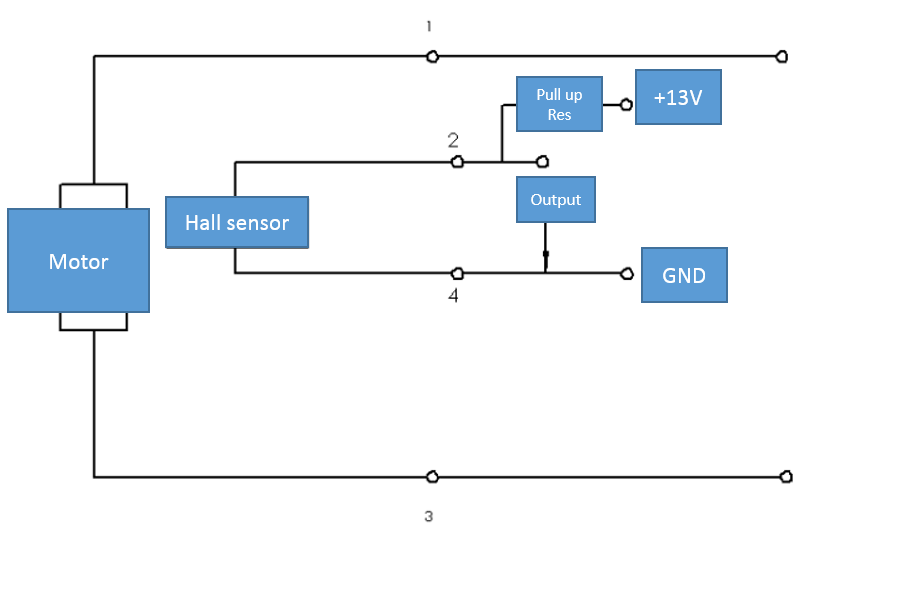
General block diagram
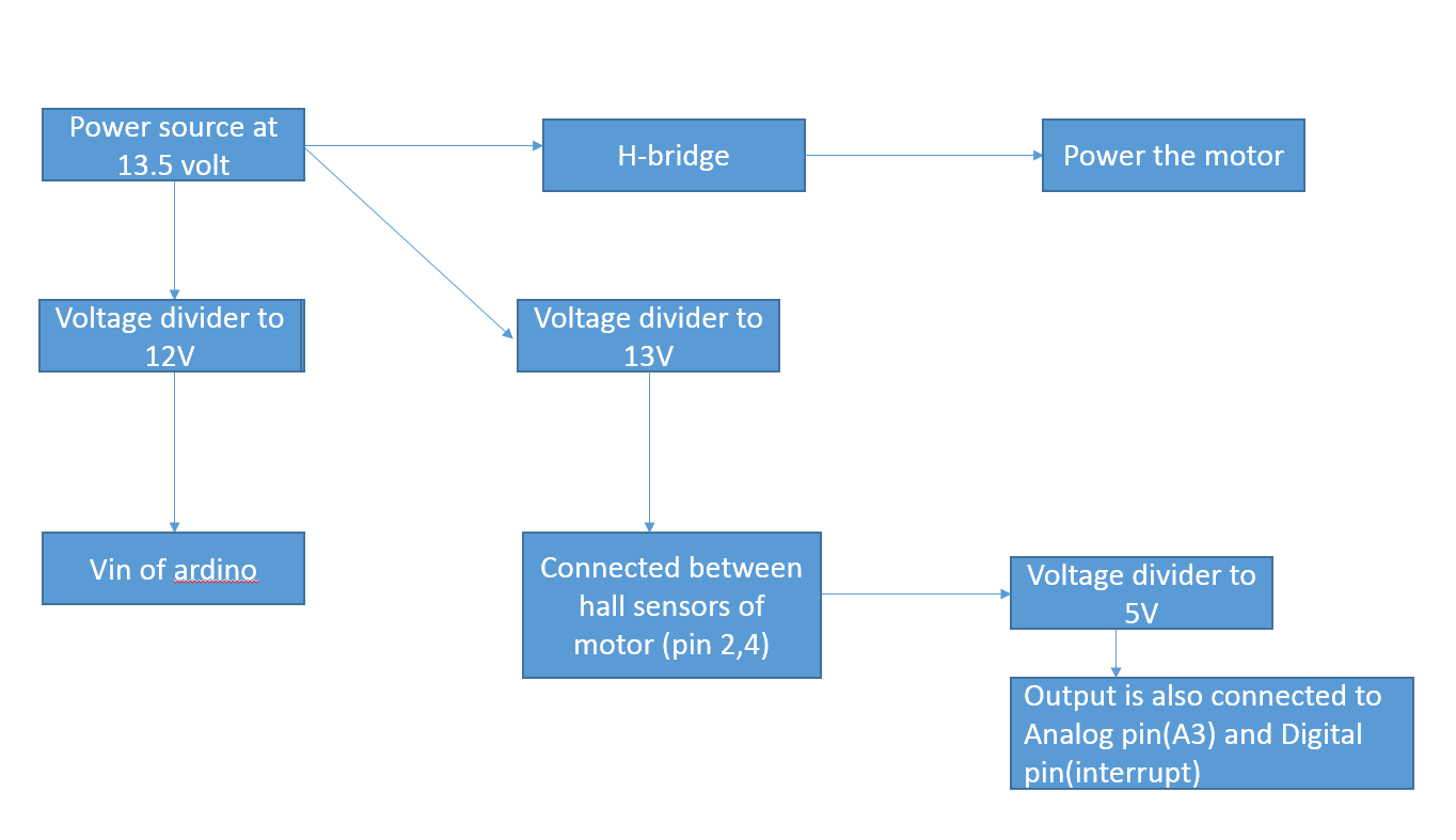
Motor with Hall sensor, Ve is 13V, Ue is 13.5V:
I print the counter (Analog pin) and pulses (interrupt pin) with running this program code.
The Analog pin reads:
CW Voltmeasure = 574
CW Voltmeasure = 588
CW Voltmeasure = 1000
CW Voltmeasure = 999
CW Voltmeasure = 998
CW Voltmeasure = 1002
CW Voltmeasure = 1002
CW Voltmeasure = 589
CW Voltmeasure = 588
CW Voltmeasure = 590
CW Voltmeasure = 588
CW Voltmeasure = 1000......by this time motor spins 6.5 rev (based on time elapsed) but counter is only @ 3 (3 highs)
Pulses read 0.......
This is where i am at. Not able to understand Analog readings dont match the number of revs with the highs & why interupt pin reads 0......
-
Any help guys? Any questions?anuzarduino– anuzarduino2016年11月29日 19:33:01 +00:00Commented Nov 29, 2016 at 19:33
-
11. Serial printing take some time. According you speed, 1 symbol takes about 1 ms, so sending "CW Voltmeasure = " by serial can take up to 16 ms (when serial buffer full) which is enough to miss one pulse.Andrey Visochan– Andrey Visochan2016年11月29日 20:48:58 +00:00Commented Nov 29, 2016 at 20:48
-
2. What 5.01 voltmeter shows when sensor switched? According logs this should be about 2.8 VAndrey Visochan– Andrey Visochan2016年11月29日 20:56:24 +00:00Commented Nov 29, 2016 at 20:56
-
And this is not enough to trigger interrupt.Andrey Visochan– Andrey Visochan2016年11月29日 21:08:30 +00:00Commented Nov 29, 2016 at 21:08
-
Andrey, are you asking to switch the connections betw hall sensor & 5.01V points?anuzarduino– anuzarduino2016年11月29日 21:10:01 +00:00Commented Nov 29, 2016 at 21:10
I tried modifying the voltages to interrupt pins
Now interrupt pin voltages read: High:1.456V Low: 1.07V
Note: The arduino is running at 12V external source.
My "pulses" counter still reads 0 for interrupts. Any idea why?
All,
My Arduino is not reading interrupts across the interrupt pin:
I am getting a high of 1.456V and a low 1.07V through the interrupt pin 2... But the pulses counter still remain 0....
Any idea why?
 volatile unsigned int pulses=0; //pulse counter
 volatile int8_t steps=0;
 int timeu=0;
 int flag=2;
 void count()
 {
 pulses++;
 }
 void setup()
 {
 // initialize serial communication:
 Serial.begin(9600);
 pinMode(11,OUTPUT);
 pinMode(12,OUTPUT);
 pinMode(13,OUTPUT);
 pinMode(2,INPUT_PULLUP);
 attachInterrupt(digitalPinToInterrupt(2),count,RISING);
 }
 void stopmotor()
 {
 digitalWrite(12,LOW);
 digitalWrite(13,LOW);
 steps=0;
 }
 void motorCCW()
 {
 analogWrite(11,255);
 digitalWrite(12,HIGH);
 digitalWrite(13,LOW);
 steps=-1;
 }
 void motorCW()
 {
 analogWrite(11,255);
 digitalWrite(12,LOW);
 digitalWrite(13,HIGH);
 steps=1;
 }
 void loop()
 {
 if (timeu<=1000)//First time - Going up
 {
 sei();
 motorCW(); //moving up
 flag=8;
 timeu++;
 }
 else if (timeu==1000)
 {
 flag=10;
 stopmotor();
 cli();
 //Serial.print("Completed time cycle of 50");
 }
 if (flag==10)
 {
 Serial.print("pulses = ");
 Serial.print(pulses);
 Serial.println();
 }
 }
-
The interrupt is triggered by a rising edge of a digital input pin, where 0V is LOW and 5V is HIGH. The threshold voltage is going to be somewhere around 2.5V. It's not intended to look for a rising analog signal, but rather a full-off transition to a full-on state. If you wish to convert your Hall Effect sensor's output to a digital LOW/HIGH signal, you may need to use a comparator (OpAmps are okay at this.)jose can u c– jose can u c2016年12月01日 14:42:41 +00:00Commented Dec 1, 2016 at 14:42
-
yes, Jose is right, according atmel specs, for 5V supply, LOW switched to HIGH when voltage grow above 3.5V and HIGH switched to LOW when voltage drops below 1.5VAndrey Visochan– Andrey Visochan2016年12月02日 14:40:37 +00:00Commented Dec 2, 2016 at 14:40
-
I think problem is either Hall sensor connection wrong or your voltage dividers interfere each other.Andrey Visochan– Andrey Visochan2016年12月02日 14:44:05 +00:00Commented Dec 2, 2016 at 14:44
-
As I understand, you Hall sensor's output is 0V near magnet and 13V other time (or vise-versa) Check this answer to see how protect you digital pin from overvoltage.Andrey Visochan– Andrey Visochan2016年12月02日 14:54:55 +00:00Commented Dec 2, 2016 at 14:54
-
The output across hall sensor is as follows: for low pulse: 7.7V to 8.8V, for high pulse: 11.3V to 13.3V. My understanding from Andrey's feedback was i need to get the high below 1.5V. My voltage divider is working good as i had changed resistors to match the required voltage. But in conclusion, i think its better to go with Jose's recommendation of a comparator to do the job.anuzarduino– anuzarduino2016年12月02日 15:13:47 +00:00Commented Dec 2, 2016 at 15:13
All,
I didnt need the voltage comparator in the end, the code was running slower and wasnt picking up all the hall sensor signals that the motor was giving due to loop time. i changed the ifs to else ifs and then i was able to get a faster loop time.
Thanks all for the help.
The device is working as intended..
pulsesis defined. Copy/paste it into your question, don't take a screenshot of it. You can format it by selecting it and pressing Ctrl+K.