I recently bought an Arduino MEGA2560 and a SainSmart InstaBots Robot Controller Shield for Arduino MEGA2560 R3 Robot Arm Control.
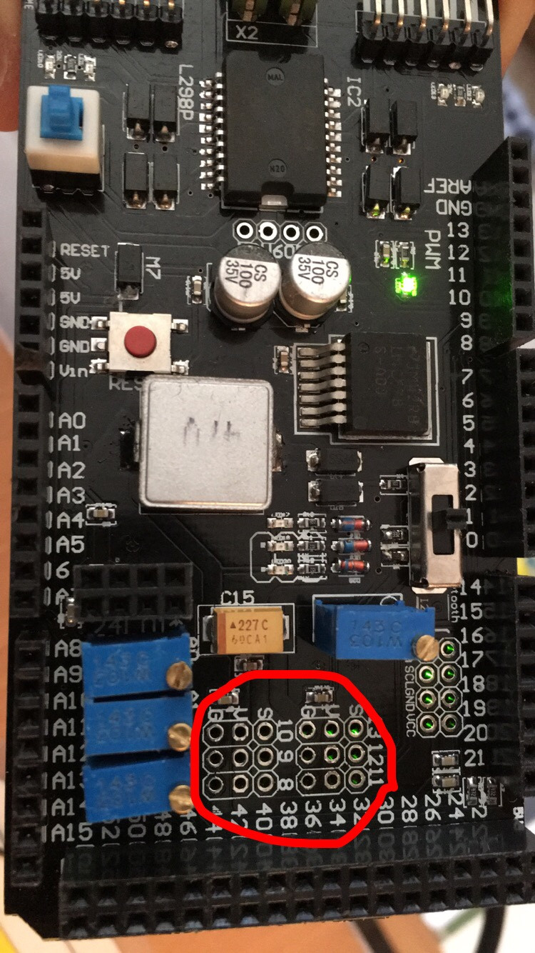
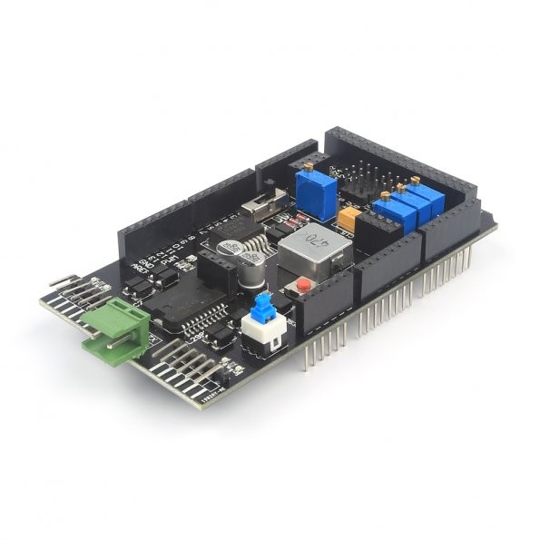
I understand how to control a servo in the method described in Sweep. However, I want to control six servos using the shield area circled in red below. Could anyone provide the code to setup and control servos from the area circled in red?
Please help me I am a beginner in robotics and I need this for a project.
-
Add more info about this shield.Mikael Patel– Mikael Patel2016年02月20日 20:52:58 +00:00Commented Feb 20, 2016 at 20:52
-
I got the shield at this link: sainsmart.com/…samuelli97– samuelli972016年02月21日 00:29:34 +00:00Commented Feb 21, 2016 at 0:29
3 Answers 3
However, I want to control six servos using the shield area circled in red below. Could anyone provide the code to setup and control servos from the area circled in red?
With the limited amount of info you have provided about the shield this will have to be a wild guess. I am assuming that the pins are S(ignal), V(cc) and G(nd) for pins 8-13. On an Arduino Mega these can be used for PWM and therefore Servo control.
Include the Servo library, attach the pin and set the angle.
#include <Servo.h>
Servo servo[6];
void setup()
{
 ...
 for (int i = 0; i < 6; i++)
 servo[i].attach(8 + i);
 ...
}
void loop()
{
 ...
 servo[i].write(pos);
 ...
}
Cheers!
NB: Do not forget to provide the correct power supply. If USB Port is left, then the upper pin is positive and the lower pin negative.
-
Wouldn't the servo.attach() number refer to the pin area near the green light?samuelli97– samuelli972016年02月21日 00:26:53 +00:00Commented Feb 21, 2016 at 0:26
-
@samuelli97 - Yes, you could use the output pins (near the green light), but for ease of use, the servos are (usually) connected to controller shields via a three pin plug, which plugs straight into the 6 sets of SVG pins, on your board. You will first need to solder 6 sets of 3 pin headers (which should have come with the board) to the PCB holes, that you have outlined in red, in order to be able to plug the servos in. As Mikael also states, you will also need to attach an external power supply to the green terminals as the Arduino can not supply enough power to the servos by itself.Greenonline– Greenonline2016年02月21日 04:24:44 +00:00Commented Feb 21, 2016 at 4:24
Sainsmart STILL refuses to supply documentation for this board.Supposedly, it can control 6 servos and two motors, up to 4 Amps, with digital encoder inputs. There is NO documentation on the hardware or the software for the mega to drive this.
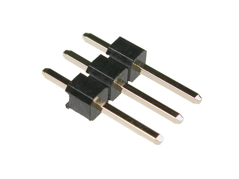
The SVG connectors on your board appear to be lacking header pins:
These should have been supplied with the board. If not you will need to source some. Either way, you will need to solder them on. I don't understand why they are not already attached.
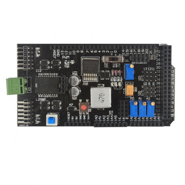
If you look at the other images of the board on the SainSmart web page, the header pins are clearly visible:
SainSmart shield with header pins
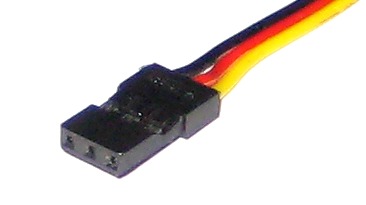
The S pin of each SVG is the same as the output pins, near the green light, but for ease of use, they are replicated in the SVG pins, so that a servo plug can be easily, and conveniently plugged in, with out the user having to wire up power and ground separately. If you look at the plug attached to the end of the cable coming from your servo, you will see the servo connector, like so:
As the board has arranged the pins in the SVG order, that means that it will support the Futaba J type connectors (but not the Airtronics, as the power and ground pins are reversed):
Futaba and Airtronics connectors
Also, Hitec and JR Radio connectors are supported by your board, as they have the same pin out:
JR Radio and HiTec connectors.
For more information, take a look at Choosing RC Servos.
In addition, as Mikael says, you will also need to attach an external power supply to the green terminals
SainSmart shield showing green external power connector
as the on board power regulator of the Arduino can not supply enough power to the servos, via the shield, by itself, neither with the USB, nor an external wall wart PSU, supplying power to the Arduino. So, use a bench power supply, battery pack, or otherwise and supply that power directly to the board via the Green power terminals at the end of the board.
Once you have done all of that, and got the hardware out of the way, then the software provided in Mikael's answer will work perfectly.
-
I have the header pins I can solder them without a problem. Do I need to connect my battery to the shield, or can I attach it to the Arduino?samuelli97– samuelli972016年02月21日 13:00:47 +00:00Commented Feb 21, 2016 at 13:00
-
Sorry you said that it has to be directly to the shield. Thank you so much!samuelli97– samuelli972016年02月21日 13:07:29 +00:00Commented Feb 21, 2016 at 13:07