Speed Line Follower Robot V4
2 10 2021This is my second line follower robot (Version 4). Unlike the previous one, I have made the design of the printed circuit (Chassis).
This is my second Line Follower Robot (Version 4). Unlike the previous one, I have made the design of the printed circuit using EasyEDA. This printed circuit acts as the chassis of the robot. The PCB manufacturing has been carried out by JLCPCB and I must say that they exceeded my expectations with impressive quality and shipment in record time.
The following video shows the final result of the prototype in which I have included the 3D models designed in Tinkercad.
In the following video I show the tests carried out with the Mini Motor Driver (MX1508).
In the next video I show the tests with the 8 CNY70 sensors. These sensors are measured analogically, through ports A0 to A7 of the Arduino Nano. I use an initial algorithm to calibrate the sensors by normalizing the range from 0 to 1000, where 0 represents the white background and 1000 the black line. Upon completing the calibration, it enters the loop and starts the reading cycle, calculating the position from 0 to 7000, which represents the left sensor to the right sensor respectively. This position value is used to calculate the proportional error P. The range of P is -3500 (left) to 3500 (right), with 0 being the center value. The algorithm memorizes the value of the position of the last sensor (left or right) that detected the black line, this with the purpose of using this data for braking actions and line recovery.
The final test with the circuit 95% mounted, is shown in the following video. A last amperage test having a maximum consumption of 200mA.
This is the latest version of the robot’s printed circuit, ready to be manufactured on JLCPCB.
This is the unboxing.
In the final stretch and already with the total of pieces, I show the assembly of my first Speed Follower Robot.
Finally and with a lot of effort I already have the fully built prototype, I show below how to load the code (Code Load Mode), how you can test the sensors and of course the tests on the track. Very happy with the operation, the test code manages to control the code very well. I have used a PID (Full) algorithm to smooth the corrections and regain the course of the line. Since everything can be improved, I will continue to play with the code to achieve a more efficient version.
As a complement, I did the simulation of this robot in the Webots application. It is still in the process of improvement but I share this video so that you can appreciate a way to perform mechanical and logical tests (Code) to control a robot in a virtual environment and that helps to understand the operation of a physically built robot.
Code to control the Speed Line Follower Robot V4
https://github.com/DrakerDG/Speed-Line-Follower-Robot/blob/master/Speed_Line_Follower_Robot_V4.ino
Comments : 2 Comments »
Tags: Arduino Nano, BitRate, EasyEDA, JLCPCB, Speed Line Follower Robot, TinkerCAD, Webots
Categories : Robots
Line Follower Robot V4
24 08 2020I present to you the advance of the robot following lines that I have worked lately.
Components:
- 1 Arduino Nano
- 1 Arduino Nano Shield
- 5 CNY70 sensors
- 2 IR Sensors GP1A01 (Similar FC-03)
- 1 Driver L298N
- 2 Motors with gearbox and encoder
- 2 Batteries 3.7V 4200mAH 18650
- 1 18650 battery holder
- 1 5V USB charger
- 1 1P1T switch 1 Pushbutton
- 1 2-tier circular acrylic chassis
- 2 Wheels covered with eva foam
- 2 Sphere wheels
- 2 double-sided perforated breadboard
- Some LEDs and SMD resistors and various connecting cables
This is one of the first functional tests, in which I included the use of the programming of the PID feedback algorithm in which at the moment I use the constants P and D.
Adjustments regarding speed control through RPM and activate the constant I are pending.
The sensors used five CNY70 and are read analogically. Initially it is necessary to calibrate the sensors for best performance (10 seconds).
The motors are powered by 2×3.7V 4200mAH 18650 batteries in series (7.4V) and for the control part (Arduino Nano) I use a 5V USB portable charger.
I include the physical design made in TinkerCAD
I have made some templates with which depending on the way they are placed, any size of track can be made. I have done 2, but the limit is imatination.
Code: DrakerDG/Line-Follower-Robot-V4
/* Line Follower 5 Analog Sensor
+ RPM Robot V2
By DrakerDG (c)
https://www.youtube.com/user/DrakerDG
*/
#include <SimplyAtomic.h>
#include <TimerOne.h>
// Speeds Motors Base
const byte SpBSE = 175;
const byte SpFWD = 135;
const byte SpREV = 180;
// Line PID constants
float Kp = 0.02; // 0.02;
float Ki = 0.00; // 0.00;
float Kd = 0.69; // 0.065;
long P=0, I=0, D=0, PIDv=0, pErr=0;
// Analog Sensor Pins
const byte pSen[5] = {14, 15, 16, 17, 18};
// Sensor Position
unsigned long PosX = 0;
// LEDs Pins
const byte pLED[3] = {9, 10, 11};
// Switch Pin
const byte pSW = 4;
// Sensor Values
int SenX[5];
// Max Sensor Samples
int MinX[5];
// Min Sensor Samples
int MaxX[5];
// On Line Status
bool detLe = false;
// Running Status
bool OnRun = false;
// Timer Counters
unsigned long Tm0 = 0;
unsigned long Tm1 = 0;
unsigned long prT = 0;
// RPM Pins
const byte PinSA = 2;
const byte PinSB = 3;
const long uSeg = 5000;
// Pulse timer counters
volatile unsigned long pwc[2];
// PWM periods
volatile unsigned long pwm[2];
// RPM values
unsigned long rpm[2];
// Left Motor Pins
const byte SML = 5;
const byte ML1 = 8;
const byte ML2 = 7;
// Right Motor Pins
const byte SMR = 6;
const byte MR1 = 13;
const byte MR2 = 12;
// Functions
void CalSnX(void);
void BlinkX(void);
void EstSnX(void);
void PosLED(void);
void CalRPM(void);
void CalPID(void);
void MoCTRL(void);
void SAcoun(void);
void SBcoun(void);
void RPMctr(void);
void setup(){
 Serial.begin(9600);

 // Left Motor Pins Setup
 pinMode(SML, OUTPUT);
 pinMode(ML1, OUTPUT);
 pinMode(ML2, OUTPUT);
 digitalWrite(SML, LOW);
 digitalWrite(ML1, LOW);
 digitalWrite(ML2, LOW);

 // Right Motor Pins Setup
 pinMode(SMR, OUTPUT);
 pinMode(MR1, OUTPUT);
 pinMode(MR2, OUTPUT);
 digitalWrite(SMR, LOW);
 digitalWrite(MR1, LOW);
 digitalWrite(MR2, LOW);
 for(byte i=0;i<3;i++){
 pinMode(pLED[i], OUTPUT);
 digitalWrite(pLED[i], LOW);
 }

 // Sensor Pins to RPM Meter
 pinMode(PinSA, INPUT);
 pinMode(PinSB, INPUT);

 // Start SW
 pinMode(pSW, INPUT);

 for (byte i=0; i<2; i++){
 pwc[i] = uSeg;
 pwm[i] = uSeg;
 rpm[i] = 0;
 }
 // Count Period Time Interrupt
 Timer1.initialize(100);
 Timer1.attachInterrupt(RPMctr);

 // RPM Motor A Sensor Interrupt
 attachInterrupt(digitalPinToInterrupt(PinSA), SAcoun, FALLING);

 // RPM Motor B Sensor Interrupt
 attachInterrupt(digitalPinToInterrupt(PinSB), SBcoun, FALLING);
 delay(1500);
 // Calibration Init
 digitalWrite(pLED[1], HIGH);
 CalSnX();
 digitalWrite(pLED[1], LOW);
 // Calibration End
 delay(500);
}
void loop(){
 if(digitalRead(pSW)) OnRun=true;
 EstSnX();
 PosLED();
 if(OnRun){
 CalRPM();
 CalPID();
 MoCTRL();
 }
}
void CalSnX(){
 Tm0 = millis();
 Tm1 = Tm0;
 unsigned long TmL;
 for(byte i=0; i<5; i++){
 SenX[i]=analogRead(pSen[i]);
 MinX[i]=SenX[i];
 MaxX[i]=SenX[i];
 }
 while((millis()-Tm0)<=10000){
 for(byte i=0; i<5; i++){
 SenX[i]=analogRead(pSen[i]);
 if(SenX[i]<MinX[i]) MinX[i]=SenX[i];
 if(SenX[i]>MaxX[i]) MaxX[i]=SenX[i];
 }
 TmL = millis();
 if ((TmL-Tm1)>=100){
 BlinkX();
 Tm1 = TmL;
 }
 }
/*
 for(byte i=0; i<5; i++){
 Serial.print(MinX[i]);
 Serial.print(" ");
 }
 Serial.println();
 for(byte i=0; i<5; i++){
 Serial.print(MaxX[i]);
 Serial.print(" ");
 }
*/
}
void BlinkX(){
 for(byte i=0;i<3;i++){
 digitalWrite(pLED[i], !digitalRead(pLED[i]));
 }
}
void EstSnX(){
 unsigned long TmE = millis();
 if ((TmE-Tm0)>10){
 detLe = false;
 unsigned long avgS = 0;
 unsigned int sumS = 0;

 for(byte i=0; i<5; i++){
 SenX[i] = analogRead(pSen[i]);
 SenX[i] = map(SenX[i], MinX[i], MaxX[i], 1000, 0);
 SenX[i] = constrain(SenX[i], 0, 1000);
 if(SenX[i]>200)detLe = true;
 if(SenX[i]>50){
 avgS += (long)SenX[i]*(i*1000);
 sumS += SenX[i];
 }
 }
 if(detLe)PosX = avgS/sumS;
 else if(PosX < 2000)PosX = 0;
 else PosX = 4000;
/*
 char DataX[60];
 sprintf(DataX,"%4d %4d %4d %4d %4d %4d ", SenX[0], SenX[1], SenX[2], SenX[3], SenX[4], PosX);
 Serial.print(DataX);
*/
 Tm0 = TmE;
 }
}
void PosLED(){
 unsigned long TmL = millis();
 if((PosX>1500)&&(PosX<2500)) digitalWrite(pLED[1], HIGH);
 else digitalWrite(pLED[1], LOW);

 if(detLe){
 if(PosX<1800) digitalWrite(pLED[0], HIGH);
 else digitalWrite(pLED[0], LOW);
 if(PosX>2200) digitalWrite(pLED[2], HIGH);
 else digitalWrite(pLED[2], LOW);
 }
 else{
 if((PosX<1800)&&((TmL-Tm1)>100)){
 digitalWrite(pLED[0], !digitalRead(pLED[0]));
 Tm1 = TmL;
 }
 if((PosX>2200)&&((TmL-Tm1)>100)){
 digitalWrite(pLED[2], !digitalRead(pLED[2]));
 Tm1 = TmL;
 }
 }

}
void SAcoun(){
 pwm[0] = pwc[0]; // Save the period
 pwc[0] = 0; // Reset the timer
}
void SBcoun(){
 pwm[1] = pwc[1]; // Save the period
 pwc[1] = 0; // Reset the timer
}
void RPMctr(){
 for (byte i=0; i<2; i++){
 // Increase the time counter
 pwc[i]++;
 if (pwc[i] > (uSeg)){
 // Limit the timer & period
 pwc[i] = uSeg;
 pwm[i] = uSeg;
 }
 }
}
void CalRPM(){
 unsigned long nwT = millis();
 // Calculations and prints every 10ms
 if ((nwT - prT) > 10){
// char sRPM[10];
 prT = nwT;
 for (byte i=0; i<2; i++){
 //RPM
 // Protects math calculation
 ATOMIC()
 {
 // Detect Rotation Decrease
 if (pwc[i]>(pwm[i]*2)){
 pwm[i] *= 2;
 pwm[i] = constrain(pwm[i], 0, uSeg);
 pwc[i] = pwc[i]*2;
 }
 /* detects or not the
 rotation of the motors */
 if (pwm[i] < uSeg) rpm[i] = 6*uSeg/pwm[i]; // Detects rotation
 else if ((rpm[i] > 0)&&(pwm[i] == uSeg)) rpm[i] = int(rpm[i]/2); // No rotatiom

 // Limits the value of RPMs
 rpm[i] = constrain(rpm[i], 0, 9999);
 }
/*
 dtostrf(rpm[i], 4, 0, sRPM);
 Serial.print(" M");
 Serial.print(i);
 Serial.print(": ");
 Serial.print(sRPM);
*/
 // Print the RPMs
 }
/*
 long RPMx = rpm[0] - rpm[1];
 dtostrf(RPMx, 4, 0, sRPM);
 Serial.print(" Delta: ");
 Serial.println(sRPM);
*/
 }
}
void CalPID(){
 P = PosX - 2000;
 I = P + pErr;
 D = P - pErr;

 PIDv = (Kp*P) + (Ki*I) + (Kd*D);
 pErr = P;
}
void MoCTRL(){
 int MoSpL = 0;
 int MoSpR = 0;
 if(detLe){
 MoSpL = SpBSE + PIDv;
 MoSpR = SpBSE - PIDv;

 MoSpL = constrain(MoSpL, 0, 255);
 MoSpR = constrain(MoSpR, 0, 255);

 digitalWrite(ML1, LOW);
 digitalWrite(ML2, HIGH);
 digitalWrite(MR1, LOW);
 digitalWrite(MR2, HIGH);
 }
 else{
 if(P==-2000){
 MoSpL = SpREV;
 MoSpR = SpFWD;
 digitalWrite(ML1, HIGH);
 digitalWrite(ML2, LOW);
 digitalWrite(MR1, LOW);
 digitalWrite(MR2, HIGH);
 }
 else if(P==2000){
 MoSpL = SpFWD;
 MoSpR = SpREV;
 digitalWrite(ML1, LOW);
 digitalWrite(ML2, HIGH);
 digitalWrite(MR1, HIGH);
 digitalWrite(MR2, LOW);
 }
 }
 char vals[28];
 sprintf(vals," L %i R %i", MoSpL, MoSpR);
 Serial.print(P);
 Serial.println(vals);
 analogWrite(SML, MoSpL);
 analogWrite(SMR, MoSpR);
}
Comments : Leave a Comment »
Tags: 18650, Arduino Nano Shield, ArduinoDroid, CNY70, DrakerDG, FC-03, GP1A01, IR Sensor, KineMaster, L298N, LED, Line Follower, Robot, TinkerCAD, YouTube
Categories : Robots
Dual Twister Ramp (Handwork)
3 12 2012This is a big versión (59 cm tall).
In this scale, the handwork is some different, like I show it in this video:
[フレーム]
In the next video, I show the DTR + in action:
[フレーム]
Comments : Leave a Comment »
Tags: cars, DTR
Categories : DTR, Model
Dual Twister Ramp + (Design)
2 12 2012This is the last design of a DTR. I add 3 levels between the floor and ceiling. This levels are interconnected with this two ramps.
This is the video of the last design of the Twister Dual Ramp +:
[フレーム]
This is a render:
This is template in PDO format : Rampa06x.pdo (Zip file)
This is PDF version file:
Comments : 7 Comments »
Tags: DTR, Metasequoia, Pepakura
Categories : 3D, Design, DTR, Metasequoia, Pepakura
Abba Cab from Carmageddon Paper Cars
26 11 2011
This is another model that you chose my little boy of 14 that are available on a page of Carmageddon papercrafts, with respective links to download.
This is the direct link to download the Abba Cab:
Both the game’s website are for anyone 18 years, the role models are beautiful. While most are simple, so much that my son picked as the Big Dump (A3), need instructions for assembling them.
For this reason I am not 100% that should unite parts where they were assembled.
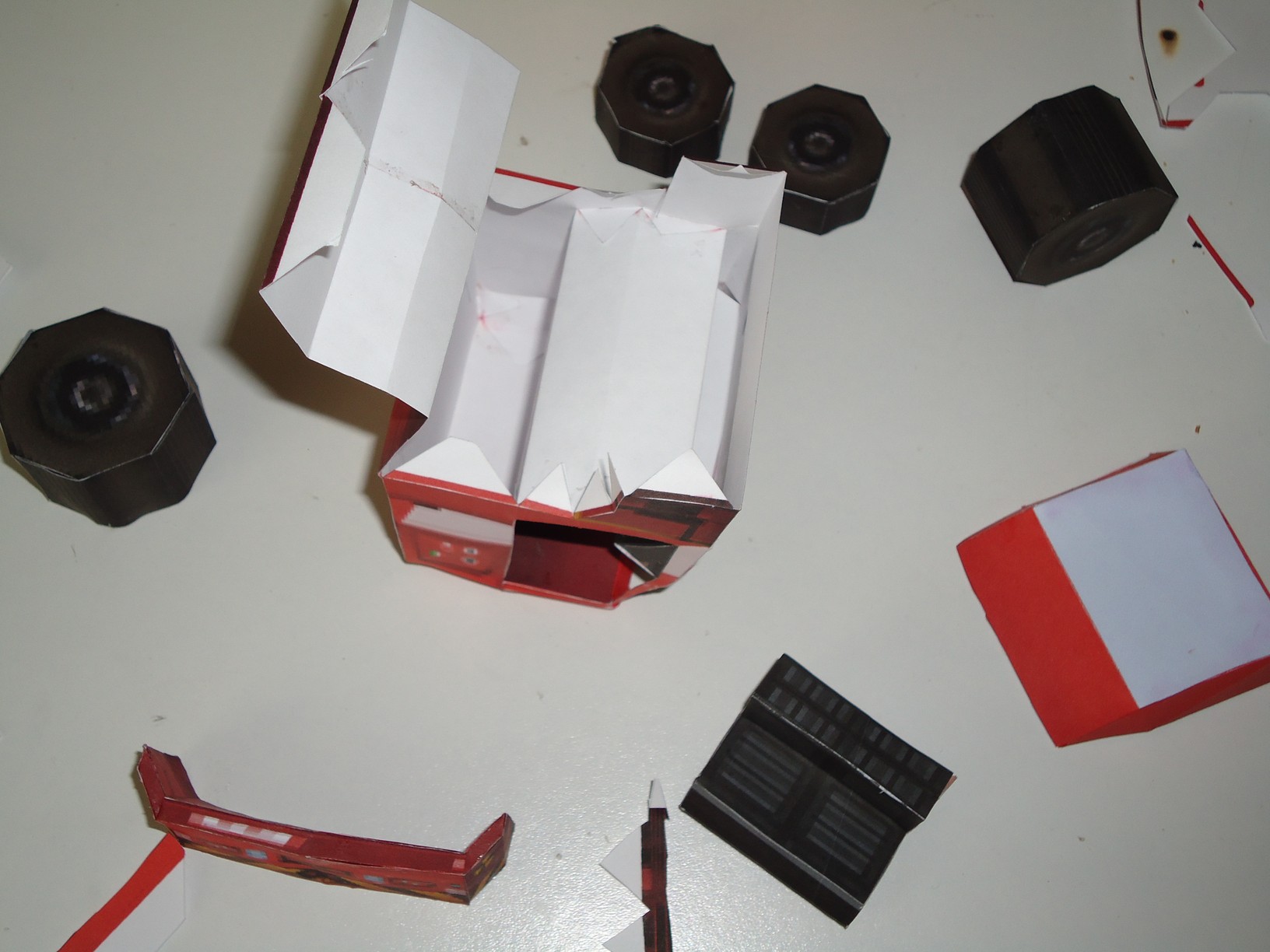
These are some pictures where I show the assembly process:
These are some pictures where you can see the finished model including a couple of buddies as passengers:
Comments : Leave a Comment »
Tags: Abba Cab, Carmageddon
Categories : Carmageddon
Thumper Cutie from disneyfamily.com
22 11 2011This model is quite simple, ideal for children. Again my son decided to make another model, cutting, folding and gluing.
This is the Thumper Cutie
This is the website where you can download the template in PDF format:
This is the direct link to download the PDF template:
In the following pictures you can see the steps to be joining parts of the model.
This model can be used as finger puppets. In the website of origin, there are other models as bamby in the same style.
Hope you like it, and my son likes.
Comments : Leave a Comment »
Tags: bamby, disney, papercraft, thumper
Categories : Disney
Dinos from PaperBox
19 11 2011These are two models of dinosaurs that are obtained from http://paperboxworld.weebly.com/dinos.html page.
My son cut, fold and paste, with the minimum possible help (with six years old).
Plant must be careful with the scissors. We recommend using special scissors for children and all under supervision.
The first is as follows:
This is the finished model:
The second model is the following:
See you next time 😉
Comments : Leave a Comment »
Tags: Dinos, PaperBox
Categories : PaperBox
Super Mario (Model)
2 02 2011From: Super Mario (Design)
Ok, I managed to finish the model of Super Mario (30 cm tall). I took a little longer than expected, since no size so hard it was to build the hands.
The following photos show the final result.
The following videos show how to put together all the parts to complete the papercraft model.
[フレーム]
[フレーム]
The model I serve as the basis for a 150cm tall. I expected a lot of work.
Templates
PDF: smario01b.pdf
PDO: 558.pdo
PDO (Mirror 1): 635.pdo
PDO (Mirror 2): Smario01B.zip
Pepakura Viewer (To PDO files): www.tamasoft.co.jp/…/viewer.html
Comments : 34 Comments »
Tags: Nintendo, Super Mario
Categories : 3D, Model, Nintendo
Lego Man (Repair legs)
31 01 2011From: Lego Man (Model)
The support legs to the hips, the effort did not tolerate for long time. The joints are very weak and broke.
These are two rolls of cardboard that will replace the original carriers, providing the strongest legs.
These are the two legs repaired.
In the following video, I show how new supports are developed and how they were placed in each leg and finish.
[フレーム]
Another is .. Like New!
Comments : 7 Comments »
Tags: Lego, Minifig
Categories : Lego, Model
Super Mario (Design)
14 01 2011
The following images are renders made from Metasequoia, which shows the dimensions achieved in 3D based on 2D views and different views on the design of the finished model.
Comments : 10 Comments »
Tags: Nintendo, Super Mario
Categories : 3D, Design, Metasequoia, Nintendo, Pepakura