Introductory Circuit Analysis (13th Edition)
Introductory Circuit Analysis (13th Edition)
13th Edition
ISBN: 9780133923605
Author: Robert L. Boylestad
Publisher: PEARSON
expand_more
expand_more
format_list_bulleted
Bartleby Related Questions Icon
Related questions
Question
Alert dont submit AI generated answer.
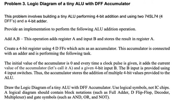
Transcribed Image Text:Problem 3. Logic Diagram of a tiny ALU with DFF Accumulator
This problem involves building a tiny ALU performing 4-bit addition and using two 74SL74 (4
DFF's) and a 4-bit adder.
Provide an implementation to perform the following ALU addition operation.
Add A,B - This operation adds register A and input B and stores the result in register A.
Create a 4-bit register using 4 D FFs which acts as an accumulator. This accumulator is connected
with an adder and is performing the following task.
The initial value of the accumulator is 0 and every time a clock pulse is given, it adds the current
value of the accumulator (let's call it A) and a given 4-bit input B. The B input is provided using
4 input switches. Thus, the accumulator stores the addition of multiple 4-bit values provided to the
ALU.
Draw the Logic Diagram of a tiny ALU with DFF Accumulator. Use logical symbols, not IC chips.
A logical diagram should contain block notations (such as Full Adder, D Flip-Flop, Decoder,
Multiplexer) and gate symbols (such as AND, OR, and NOT).
Expert Solution
Check MarkThis question has been solved!
Explore an expertly crafted, step-by-step solution for a thorough understanding of key concepts.
bartleby
This is a popular solution
bartleby
Trending nowThis is a popular solution!
bartleby
Step by stepSolved in 3 steps with 2 images
Knowledge Booster
Background pattern image
Learn more about
Need a deep-dive on the concept behind this application? Look no further. Learn more about this topic, electrical-engineering and related others by exploring similar questions and additional content below.Similar questions
- What is the minimum distance between conduits in a junction box straight through pull? A. 6 times the diameter of the largest raceway B. 8 times... C. 10 times... D. 12 times...arrow_forwardThe system having ±0.5% of F.S.D if the full scale deflection is 50 units, then accuracy is _____ a. ±0.25 b. ±1 c. ±0 d. ±0.5arrow_forward(c) Draw a circuit diagram to represent a TN-C-S earthing system and briefly explain its advantages and disadvantages. (d) Briefly explain how to estimate the height of air termination of a lightning protection system network using the rolling sphere method and protection angle method. (e) Briefly explain what is meant by Ground Potential Rise (GPR) and explain why an animal like cow would not be adequately protected against GPR. Note : answer all or else dnt attempt the questionarrow_forward
- Fill in the Blanks: Q: If an input signal is bounded, then the output signal must also be bounded, if the system is _____________________ system.arrow_forwardConsider a home heating system consisting of a natural gas-fired furnace and a ther- mostat. In this case the process consists of the interior space to be heated. The ther- mostat contains both the measuring element and the controller. The furnace is either on (heating) or off. Draw a schematic diagram for this control system. On your diagram, identify the process outputs and all inputs, including disturbance variables.arrow_forwardController Load Could you please briefly tell me what this circuit stands for?arrow_forward
- Consider as a simple telephone network consisting of two end workplacesand one intermediate switch with a 1 MHz full duplex trunk between eachend workplace and the intermediate switch. Assume a 4 kHz channel foreach voice call. The telephone is used to make four calls per 8 hour workdayin average, with mean call duration of five minutes. Twelve percent of thecalls are long distance. Analyse and determine the maximum number oftelephones an end workplace can support. Note: Please explain the answer process clearly.arrow_forwardWhat is the main goal of Synchronization System? Which are the main components of the System?arrow_forwardUsing the notation scheme for defining manipulator configurations, draw diagrams of the following robots. Label each joint in the diagram. (i) TVR:TR (ii) VROT:Rarrow_forward
- Please answer in typing format solution please only Please answer all subparts is compulsory to answer in your Please I will like it pleasearrow_forwardThe PLC-5, SLC 500, and MicroLogix use a(n) ____________________ instruction for moving data from one word to another.arrow_forwardQ.Explain sources of noise and its type(electrical amd static noise) in detail?Explain magnetic noise in detail ?Explain crosstalk,shielding and grounding in detail ?Explain level measurement(mechanical level indicators) in detail?arrow_forward
arrow_back_ios
SEE MORE QUESTIONS
arrow_forward_ios
Recommended textbooks for you
- Text book imageIntroductory Circuit Analysis (13th Edition)Electrical EngineeringISBN:9780133923605Author:Robert L. BoylestadPublisher:PEARSONText book imageDelmar's Standard Textbook Of ElectricityElectrical EngineeringISBN:9781337900348Author:Stephen L. HermanPublisher:Cengage LearningText book imageProgrammable Logic ControllersElectrical EngineeringISBN:9780073373843Author:Frank D. PetruzellaPublisher:McGraw-Hill Education
- Text book imageFundamentals of Electric CircuitsElectrical EngineeringISBN:9780078028229Author:Charles K Alexander, Matthew SadikuPublisher:McGraw-Hill EducationText book imageElectric Circuits. (11th Edition)Electrical EngineeringISBN:9780134746968Author:James W. Nilsson, Susan RiedelPublisher:PEARSONText book imageEngineering ElectromagneticsElectrical EngineeringISBN:9780078028151Author:Hayt, William H. (william Hart), Jr, BUCK, John A.Publisher:Mcgraw-hill Education,
Text book image
Introductory Circuit Analysis (13th Edition)
Electrical Engineering
ISBN:9780133923605
Author:Robert L. Boylestad
Publisher:PEARSON
Text book image
Delmar's Standard Textbook Of Electricity
Electrical Engineering
ISBN:9781337900348
Author:Stephen L. Herman
Publisher:Cengage Learning
Text book image
Programmable Logic Controllers
Electrical Engineering
ISBN:9780073373843
Author:Frank D. Petruzella
Publisher:McGraw-Hill Education
Text book image
Fundamentals of Electric Circuits
Electrical Engineering
ISBN:9780078028229
Author:Charles K Alexander, Matthew Sadiku
Publisher:McGraw-Hill Education
Text book image
Electric Circuits. (11th Edition)
Electrical Engineering
ISBN:9780134746968
Author:James W. Nilsson, Susan Riedel
Publisher:PEARSON
Text book image
Engineering Electromagnetics
Electrical Engineering
ISBN:9780078028151
Author:Hayt, William H. (william Hart), Jr, BUCK, John A.
Publisher:Mcgraw-hill Education,