Delmar's Standard Textbook Of Electricity
Delmar's Standard Textbook Of Electricity
7th Edition
ISBN: 9781337900348
Author: Stephen L. Herman
Publisher: Cengage Learning
expand_more
expand_more
format_list_bulleted
Bartleby Related Questions Icon
Related questions
Question
Please solve the chart and answer the questions please. Thank you!!
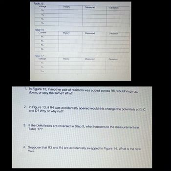
Transcribed Image Text:Table 15
Voltage
Theory
Measured
Deviation
VA
VB
Vc
V1
Table 16
Current
Theory
Measured
Deviation
R1
R2
R
Re
Table 17
Voltage
Theory
Measured
Deviation
VA
Vo
VAB
1. In Figure 13, if another pair of resistors was added across R6, would Vo go up,
down, or stay the same? Why?
2. In Figure 13, if R4 was accidentally opened would this change the potentials at B, C
and D? Why or why not?
3. If the DMM leads are reversed in Step 5, what happens to the measurements in
Table 17?
4. Suppose that R3 and R4 are accidentally swapped in Figure 14. What is the new
VAB?
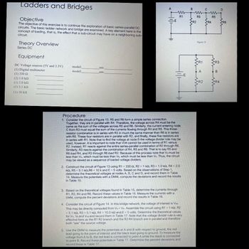
Transcribed Image Text:Ladders and Bridges
Objective
The objective of this exercise is to continue the exploration of basic series-parallel DC
circuits. The basic ladder network and bridge are examined. A key element here is the
concept of loading, that is, the effect that a sub-circuit may have on a neighboring sub-
circuit.
Theory Overview
Series DC
Equipment
DC Voltage sources (5V and 3.3V)
(1) Digital multimeter
(1) 330 Ω
model:
model:
srn:
srn:
(2) 1.0 ΚΩ
(1) 2.0 ΚΩ
(1) 5.1 ΚΩ
(1) 10 ΚΩ
B
www
w
ww
R1
R3
R5
R2
Procedure
1. Consider the circuit of Figure 13. R5 and R6 form a simple series connection.
Together, they are in parallel with R4. Therefore, the voltage across R4 must be the
same as the sum of the voltages across R5 and R6. Similarly, the current entering node
C from R3 must equal the sum of the currents flowing through R4 and R5. This three-
resistor combination is in series with R3 in much the same manner than R6 is in series
with R5. These four resistors are in parallel with R2, and finally, these five resistors are
in series with R1. Note that to find the voltage at node B the voltage divider rule may be
used, however, it is important to note that VDR cannot be used in terms of R1 versus
R2. Instead, R1 reacts against the entire series-parallel combination of R2 through R6.
Similarly, R3 reacts against the combination of R4, R5 and R6. That is to say R5 and
R6 load R4, and R3 through R6 load R2. Because of this process note that Vo must be
less than Vc, which must be less than Va, which must be less than VA. Thus, the circuit
may be viewed as a sequence of loaded voltage dividers.
=
2. Construct the circuit of Figure 13 using R1 330 Q, R2 = 1 ko, R3 = 1.0 k2, R4 = 2.0
kQ, R5 5.1 kQ,R6 = 10 k and E = 5 volts. Based on the observations of Step 1,
determine the theoretical voltages at nodes A, B, C and D, and record them in Table
14. Measure the potentials with a DMM, compute the deviations and record the results
in Table 15.
3. Based on the theoretical voltages found in Table 15, determine the currents through
R1, R2, R4 and R6. Record these values in Table 16. Measure the currents with a
DMM, compute the percent deviations and record the results in Table 16.
4. Consider the circuit of Figure 14. In this bridge network, the voltage of interest is VA.
This may be directly computed from VA- Vs. Assemble the circuit using R1 = 1 kg, R2
= 5.1 km, R3 = 5.1 k2, R4 = 10.0 k2 and E = 5 volts. Determine the theoretical values
for VA, Ve and VAB and record them in Table 17. Note that the voltage divider rule is very
effective here as the R1 R2 branch and the R3 R4 branch are in parallel and therefore
both "see" the source voltage.
5. Use the DMM to measure the potentials at A and B with respect to ground, the red
lead going to the point of interest and the black lead going to ground. To measure the
voltage from A to B, the red lead is connected to point A while the black is connected
to point B. Record these potentials in Table 17. Determine the percent deviations and
record these in Table 17.
Figure 13
R1
B
Expert Solution
Check MarkThis question has been solved!
Explore an expertly crafted, step-by-step solution for a thorough understanding of key concepts.
bartleby
Step by stepSolved in 2 steps with 7 images
Knowledge Booster
Background pattern image
Recommended textbooks for you
- Text book imageDelmar's Standard Textbook Of ElectricityElectrical EngineeringISBN:9781337900348Author:Stephen L. HermanPublisher:Cengage LearningText book imagePower System Analysis and Design (MindTap Course ...Electrical EngineeringISBN:9781305632134Author:J. Duncan Glover, Thomas Overbye, Mulukutla S. SarmaPublisher:Cengage LearningText book imageElectricity for Refrigeration, Heating, and Air C...Mechanical EngineeringISBN:9781337399128Author:Russell E. SmithPublisher:Cengage Learning
- Text book imageEBK ELECTRICAL WIRING RESIDENTIALElectrical EngineeringISBN:9781337516549Author:SimmonsPublisher:CENGAGE LEARNING - CONSIGNMENTText book image
Text book image
Delmar's Standard Textbook Of Electricity
Electrical Engineering
ISBN:9781337900348
Author:Stephen L. Herman
Publisher:Cengage Learning
Text book image
Power System Analysis and Design (MindTap Course ...
Electrical Engineering
ISBN:9781305632134
Author:J. Duncan Glover, Thomas Overbye, Mulukutla S. Sarma
Publisher:Cengage Learning
Text book image
Electricity for Refrigeration, Heating, and Air C...
Mechanical Engineering
ISBN:9781337399128
Author:Russell E. Smith
Publisher:Cengage Learning
Text book image
EBK ELECTRICAL WIRING RESIDENTIAL
Electrical Engineering
ISBN:9781337516549
Author:Simmons
Publisher:CENGAGE LEARNING - CONSIGNMENT
Text book image