Introductory Circuit Analysis (13th Edition)
Introductory Circuit Analysis (13th Edition)
13th Edition
ISBN: 9780133923605
Author: Robert L. Boylestad
Publisher: PEARSON
expand_more
expand_more
format_list_bulleted
Bartleby Related Questions Icon
Related questions
Question
Draw in Table 3 the circuit schematic of each segment using the basic logic gates in kmap
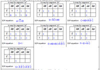
Transcribed Image Text:k-map for segment "a"
k-map for segment "b"
k-map for segment "c"
AB AB AB ĀB
AB AB AB ĀB
AB AB AB ĀB
1
1
1
1
1
1
1
C lo
1
1
SOP equation:
b= AC+AB
SOP equation: C=AB+ĀB C
SOP equation:
a= C+B
k-map for segment "d"
k-map for segment "e"
k-map for segment "f"
AB AB AB ĀB
АВ | АВ АВ | АВ
AB AB AB ĀB
1
1
1
1
1
1
1
1
1
1
1
1
1
1
1
SOP equation
SOP equation E=AB+BC+A B C
SOP equation F= B +AC
D=1
k-map for segment
AB AB AB ĀB
SOP equation G= ĀB C+A B C
Transcribed Image Text:Having the SOP equation for each segment, we are going to construct the logic circuit for each segment.
9. For each SOP equation in Table 2, list in Table 3 the basic logic gates that are required to build the
logic circuit. Remember that AND gate is used for multiplication, OR gate is used for addition, and NOT
gate is used for inversion. Here is the code reference for some of the basic gates
B 74LSO8 = 2-input AND gate (quad)
B 74LS32 = 2-input OR gate (quad)
E 74LS04 = NOT gate (hex)
E 74LS11 = 3-input AND gate (triple)
E 74LS00 = 2-input NAND gate (quad)
B 74LSO2 = 2-input NOR gate (quad)
8 74LS86 = 2-input XOR gate (quad)
a 747266 = 2-input XNOR gate (quad)
E 74LS133 = 13-input NAND gate (single)
10. Draw in Table 3 the circuit schematic of each segment using the basic logic gates in step7
Segment
Basic logic gates needed
Circuit Schematic According
to SOP equation in Table 2
a
b
d
e
f
Table 3 - Logic gates needed for each segment of a 7-segment display
bo
Expert Solution
Check MarkThis question has been solved!
Explore an expertly crafted, step-by-step solution for a thorough understanding of key concepts.
bartleby
Step by stepSolved in 2 steps with 3 images
Knowledge Booster
Background pattern image
Learn more about
Need a deep-dive on the concept behind this application? Look no further. Learn more about this topic, electrical-engineering and related others by exploring similar questions and additional content below.Similar questions
- Using appropriate diagrams, explain how a combination of transistors and resistors would be used to construct an OR logic gate to control the flow of electrons inside an integrated circuit. please show mw how to do the digramarrow_forwardDesign a combinational circuit using multiplexer for a car chime based on thefollowing system: A car chime or bell will sound if the output of the logic circuit(X) is set to a logic ‘1’. The chime is to be sounded for either of the followingconditions:• if the headlights are left on when the engine is turned off and• if the engine is off and the key is in the ignition when the door is opened.Use the following input names and nomenclature in the design process:• ‘E’ – Engine. ‘1’ if the engine is ON and ‘0’ if the engine is OFF• ‘L’ – Lights. ‘1’ if the lights are ON and ‘0’ if the lights are OFF• ‘K’ – Key. ‘1’ if the key is in the ignition and ‘0’ if the key is not in the ignition• ‘D’ – Door. ‘1’ the door is open and ‘0’ if the door is closed• ‘X’ – Output to Chime. ‘1’ is chime is ON and ‘0’ if chime is OFFarrow_forwardQuestion 1) If six NOT (inverters) gates are connected in series and the input to the first gate is a LOW (0) the output of the FIFTH. gate will be:arrow_forward
- Please do part b using the Assumptionarrow_forwardDraw the output waveform C and D, given the input waveforms A and B as shown belowfigure 2.Figure 2b) Verify the result from part (a) by any using simulation tools. (Screen shoot only for thefollowing input cases: when (A=0, B=0), (A=1, B=0) and (A=0, B=1). c) For the logic circuit given in Figure 3, obtain the output expression for ?arrow_forwardImplement the logic circuit in Figure 2 using only NAND gate A B C Xarrow_forward
- A single phase half-bridge voltage source inverter (VSI) has a resistive load of 2.4Ω andinput dc voltage Vdc = 48V. The desired fundamental frequency of the load voltage is 50 Hz.Determine: RMS output voltage at fundamental frequency and voltage rating of switchesarrow_forward30) Coils labeled ( S ) and ( R )A) must appear in that order (S before R) in a ladder logic programB) may be used only in subroutines in programs for Siemens PLCsC) are Short and Repeated coils, used in timing programsD) may be used instead of a seal-in arrangement to provide latchingarrow_forwardUsing appropriate diagrams, explain how a combination of transistors and resistors would be used to construct an OR logic gate to control the flow of electrons inside an integrated circuit. please show mw how to do the digramarrow_forward
- Below is an example of an NMOS logic circuit. For all of the MOSFETs in the circuit below, assume V = 1 V and k = 50 mA/V2. th W R2 = 5600 PEETHIPPIN R1 - 4700 M3 M1 M. 0 a. Indicate and verify the state of each MOSFET and V for the following input combinations. Fill-out the table below for each assumed state of the MOSFET for every input combination. Use R approximation for linear operation and three significant ds(on) figures for the voltages. 오 Ao SV whyarrow_forwardLOGIC GATE ( NEED ONLY HANDWRITTEN SOLUTION PLEASE OTHERWISE DOWNVOTE).arrow_forward5) Draw the circuit diagram using diode and write the truth table of a logic gates whose output will be the logical OR operation of two inputs.arrow_forward
arrow_back_ios
SEE MORE QUESTIONS
arrow_forward_ios
Recommended textbooks for you
- Text book imageIntroductory Circuit Analysis (13th Edition)Electrical EngineeringISBN:9780133923605Author:Robert L. BoylestadPublisher:PEARSONText book imageDelmar's Standard Textbook Of ElectricityElectrical EngineeringISBN:9781337900348Author:Stephen L. HermanPublisher:Cengage LearningText book imageProgrammable Logic ControllersElectrical EngineeringISBN:9780073373843Author:Frank D. PetruzellaPublisher:McGraw-Hill Education
- Text book imageFundamentals of Electric CircuitsElectrical EngineeringISBN:9780078028229Author:Charles K Alexander, Matthew SadikuPublisher:McGraw-Hill EducationText book imageElectric Circuits. (11th Edition)Electrical EngineeringISBN:9780134746968Author:James W. Nilsson, Susan RiedelPublisher:PEARSONText book imageEngineering ElectromagneticsElectrical EngineeringISBN:9780078028151Author:Hayt, William H. (william Hart), Jr, BUCK, John A.Publisher:Mcgraw-hill Education,
Text book image
Introductory Circuit Analysis (13th Edition)
Electrical Engineering
ISBN:9780133923605
Author:Robert L. Boylestad
Publisher:PEARSON
Text book image
Delmar's Standard Textbook Of Electricity
Electrical Engineering
ISBN:9781337900348
Author:Stephen L. Herman
Publisher:Cengage Learning
Text book image
Programmable Logic Controllers
Electrical Engineering
ISBN:9780073373843
Author:Frank D. Petruzella
Publisher:McGraw-Hill Education
Text book image
Fundamentals of Electric Circuits
Electrical Engineering
ISBN:9780078028229
Author:Charles K Alexander, Matthew Sadiku
Publisher:McGraw-Hill Education
Text book image
Electric Circuits. (11th Edition)
Electrical Engineering
ISBN:9780134746968
Author:James W. Nilsson, Susan Riedel
Publisher:PEARSON
Text book image
Engineering Electromagnetics
Electrical Engineering
ISBN:9780078028151
Author:Hayt, William H. (william Hart), Jr, BUCK, John A.
Publisher:Mcgraw-hill Education,