Introductory Circuit Analysis (13th Edition)
Introductory Circuit Analysis (13th Edition)
13th Edition
ISBN: 9780133923605
Author: Robert L. Boylestad
Publisher: PEARSON
expand_more
expand_more
format_list_bulleted
Bartleby Related Questions Icon
Related questions
Question
please show work
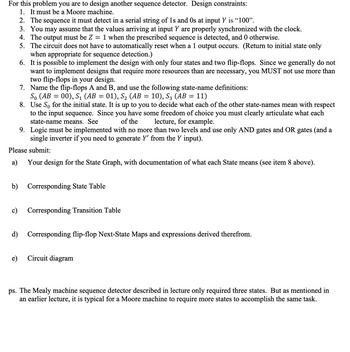
Transcribed Image Text:For this problem you are to design another sequence detector. Design constraints:
1. It must be a Moore machine.
9. Logic must be implemented with no more than two levels and use only AND gates and OR gates (and a
single inverter if you need to generate Y' from the Y input).
Please submit:
a) Your design for the State Graph, with documentation of what each State means (see item 8 above).
2. The sequence it must detect in a serial string of 1s and Os at input Y is "100".
3. You may assume that the values arriving at input Y are properly synchronized with the clock.
4. The output must be Z 1 when the prescribed sequence is detected, and 0 otherwise.
=
5. The circuit does not have to automatically reset when a 1 output occurs. (Return to initial state only
when appropriate for sequence detection.)
6. It is possible to implement the design with only four states and two flip-flops. Since we generally do not
want to implement designs that require more resources than are necessary, you MUST not use more than
two flip-flops in your design.
7. Name the flip-flops A and B, and use the following state-name definitions:
So (AB = 00), S1 (AB 01), S2 (AB = 10), S3 (AB = 11)
8.
Use So for the initial state. It is up to you to decide what each of the other state-names mean with respect
to the input sequence. Since you have some freedom of choice you must clearly articulate what each
state-name means. See
of the
lecture, for example.
b) Corresponding State Table
c)
e)
Corresponding Transition Table
d) Corresponding flip-flop Next-State Maps and expressions derived therefrom.
Circuit diagram
ps. The Mealy machine sequence detector described in lecture only required three states. But as mentioned in
an earlier lecture, it is typical for a Moore machine to require more states to accomplish the same task.
Expert Solution
Check MarkThis question has been solved!
Explore an expertly crafted, step-by-step solution for a thorough understanding of key concepts.
bartleby
Step by stepSolved in 3 steps with 3 images
Knowledge Booster
Background pattern image
Learn more about
Need a deep-dive on the concept behind this application? Look no further. Learn more about this topic, electrical-engineering and related others by exploring similar questions and additional content below.Similar questions
- Please answer with detail and how it is done. Photo is attached with the questions.arrow_forwardWhere a 2 1/2 inch conduit enters an angle pull box with three 400 MCM type THHN conductors and a 2 1/2 inch conduit leaves a pull box oposite the cover, what is the minimum size pull box requiredarrow_forwardWhat is the specific procedure for clearing an EPROM for the first time?arrow_forward
- 5arrow_forwardVdc0 U=12 V Circuit #1 Ried V LED www Ried_series 0.05 Vdc0 U = 12 V 0,04 Circuit 0.03 0.02 0.01 RED LED GREEN LE Set current to 10 mA LED voltages Given the circuit #1 presented above, answer the following questions: BLUE_LEC Red 0.5 1) Determine the value of the V1 (voltage forward of the LED) for the LEDS RED, VDRED GREEN, VREEN and BLUE, VOBLUES when the current through the LEDs is 10mA, 2) Is the LED in Circuit #1, connected in the way that will be lighting up or not - Justify your answer Green 3) Calculate the value of the resistance Rled in Circuit #1, to ensure that a RED LED will have a current of 10 mA 1.5 2 25 Voltage across LED (V) 4) Calculate the value of the resistance Rled in Circuit #1, to ensure that a GREEN LED will have a current of 10 mA Blue 5) Calculate the value of the resistance Rled in Circuit #1, to ensure that a Blue LED will have a current of 10 mA 6) Given three LEDs, connected in series as shown in the Circui # 2 (below), calculate the value of the...arrow_forwardElectric Powers System for Nonelectrical Professional Can you tell me how circuit breakers and diconnect switches are used to isolate equipmentarrow_forward
- Repeat above (insert image) with the resistors in parallel, insert multitesters (digital or analog) to measure current along each resistor. Comment on the meter readings and set up.arrow_forwardCan you tell me what kind of cords use the F connector?arrow_forwardThe waveform of a voltage source is shown in the given figure. Let A = 2 and B = -3.8. Determine the average current supplied to a 10-ohm resistor connected across the voltage source. The average current supplied to a 10-ohm resistor connected across the voltage source is ______A.arrow_forward
- In the image below the cylinder has a radius of 0.4 meters and a height of 0.8 meters. A non-uniform electric field exist in space of the form. ECX, y, z) = (800 (N/ (C m) y (200 (N/ C) j A) What is the flux through the very top, the sides, and the bottom surfaces of the image. B) Total amount of charge inside the image. Focus 目 84 F HEarrow_forwardWhat is the importance of a clear labeling system for panelboards?arrow_forward
arrow_back_ios
arrow_forward_ios
Recommended textbooks for you
- Text book imageIntroductory Circuit Analysis (13th Edition)Electrical EngineeringISBN:9780133923605Author:Robert L. BoylestadPublisher:PEARSONText book imageDelmar's Standard Textbook Of ElectricityElectrical EngineeringISBN:9781337900348Author:Stephen L. HermanPublisher:Cengage LearningText book imageProgrammable Logic ControllersElectrical EngineeringISBN:9780073373843Author:Frank D. PetruzellaPublisher:McGraw-Hill Education
- Text book imageFundamentals of Electric CircuitsElectrical EngineeringISBN:9780078028229Author:Charles K Alexander, Matthew SadikuPublisher:McGraw-Hill EducationText book imageElectric Circuits. (11th Edition)Electrical EngineeringISBN:9780134746968Author:James W. Nilsson, Susan RiedelPublisher:PEARSONText book imageEngineering ElectromagneticsElectrical EngineeringISBN:9780078028151Author:Hayt, William H. (william Hart), Jr, BUCK, John A.Publisher:Mcgraw-hill Education,
Text book image
Introductory Circuit Analysis (13th Edition)
Electrical Engineering
ISBN:9780133923605
Author:Robert L. Boylestad
Publisher:PEARSON
Text book image
Delmar's Standard Textbook Of Electricity
Electrical Engineering
ISBN:9781337900348
Author:Stephen L. Herman
Publisher:Cengage Learning
Text book image
Programmable Logic Controllers
Electrical Engineering
ISBN:9780073373843
Author:Frank D. Petruzella
Publisher:McGraw-Hill Education
Text book image
Fundamentals of Electric Circuits
Electrical Engineering
ISBN:9780078028229
Author:Charles K Alexander, Matthew Sadiku
Publisher:McGraw-Hill Education
Text book image
Electric Circuits. (11th Edition)
Electrical Engineering
ISBN:9780134746968
Author:James W. Nilsson, Susan Riedel
Publisher:PEARSON
Text book image
Engineering Electromagnetics
Electrical Engineering
ISBN:9780078028151
Author:Hayt, William H. (william Hart), Jr, BUCK, John A.
Publisher:Mcgraw-hill Education,